Minimizing power requirements while maximizing performance tends to be on everyone’s checklist these days. But, like security technology, there is a lot of misunderstanding and even more new technology that many designers have yet to encounter.
Developers now need to pay closer attention to details like static versus dynamic power. Static power is needed to start a device, while dynamic power changes based on the operations and peripherals involved to get work done.
They should still remember simple recommendations like using high-resistance pull-up resistors on I/O pins, especially for unused devices that cannot be turned off completely. The nanoamps saved by software gymnastics often can be undone by not employing these simple techniques.
This file type includes high resolution graphics and schematics when applicable.
Power Debugging And Virtualization
Many designers tend to assume that a hardware solution alone will address their needs for power efficiency. It might require the use of a couple of power-down modes, but that is often it for many projects. However, software development can play a key role too.
One of the biggest changes on the software side is the use of power debugging. This is not something for power users, although they might use the tools, but rather debuggers that have hooks into the power utilization monitors.
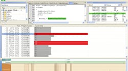
For example, IAR Systems’ power debugger (Fig. 1) allows developers to locate program “hot spots” (see “Power Debugger Finds Hot Spots” at electronicdesign.com). It normally works with a single current-sensing input that provides overall system power use. Developers can match the power usage to a particular line of code, although this is based on a combination of factors including the state of peripherals. Still, the feedback is usually useful in determining how power is utilized.
The power information is just one more piece of data that can be used for breakpoints and tracing. Breakpoints can check if power usage is higher or lower than a specified limit. Typically, a trace provides a power utilization graph. The trace is often used to apply a threshold value so the programmer can see what code was active during high-energy usage. This approach can be used to see the results of changes in power modes and other power reduction techniques.
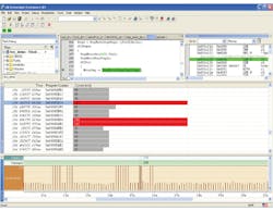
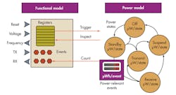
Testing real hardware is not the only way to check out power utilization. It can be done using virtual hardware as well such as the Synopsys Virtualizer Development Kit (VDK). It allows power estimation based on a virtual machine implementation (Fig. 2) so developers can see how a system will react before the hardware is available (see “Kit Generates Virtual Platforms With Power Debugging Support” at electronicdesign.com). The same type of experimentation can be performed with the virtual hardware so power-efficient software is ready when the hardware becomes available.
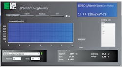
One way to determine whether hardware can provide the power optimizations necessary for an application is to use power-based benchmarks. The Embedded Microprocessor Benchmark Consortium (EEMBC) has delivered a wide range of benchmarks like CoreMark. EEMBC also has one for ultra-low-power microcontrollers and processors (see “Interview: Markus Levy Discusses The EEMBC Ultra Low Power Benchmark” at electronicdesign.com). The EEMBC ULPBench (Ultra Low Power Benchmark) is a series of tests (Fig. 3).
Benchmarks can be useful in determining whether a particular platform can provide the kind of power reduction techniques needed for an application. It also can be used to determine if a particular platform is more or less efficient than an existing application platform implementation.
Run Modes And Clocks
Back in the dark ages, developers generally were limited to choosing a clock frequency to adjust the amount of power consumed by the system. Power consumption was less of an issue given the limited number of mobile devices in play. These days, developers operate at the opposite extreme with multiple ways of reducing power consumption. Applications and operating systems can twiddle with operating voltages and clock frequencies.
Developers often have the choice of clock and power sources as well, adding more complexity to the mix. For example, very low-power, on-chip clocks are often available on microcontrollers, but their accuracy may be limited compared to off-chip crystals.
Systems are also partitioned, allowing the use of clock gating and power isolation in multiple regions. Many newer systems employ a large number of regions providing very fine grain control. Managing all these features can be a challenge to developers who are just trying to get a job done.
Run modes provide a tradeoff between simple management and control of a complex collection of settings. A typical microcontroller may have a few to a dozen run modes that have different characteristics that affect clock rate, operating voltages, and peripheral capabilities. These modes tend to address bursty operation of many applications where high-performance compute or high-power peripherals are required for a short time period. The system then can operate using minimal power until computation or communication is required.
In general, slower means lower power, but this really depends on the application and system. Slower operation means that computation or communication needs to proceed more slowly, taking a longer time to get a particular job done. This may be the best option if the overall power utilization is better, but in many instances faster may better. It all depends on the overall power efficiency as well as the types of the available run modes and the type of work that needs to be done.
Freescale’s KL03 has a compute mode that turns off most peripherals and only runs the memory and CPU (see “How Small A Chip Will A 32-bit Micro Fit In?” at electronicdesign.com). This is handy if lots of computation is needed, such as post-processing of a message or peripheral operation. A system might use a low-power sleep mode while waiting on an event, wake up and process and event when it occurs, switch to compute mode to finish the operation, save the results, and return to the sleep mode.
There ain’t no such thing as a free lunch (TANSTAAFL) when selecting modes and configurations. The plethora of options makes selection a challenge. Nothing is free when it comes to power, computation, and even storage. Microchip’s nanoWatt XLP technology has a deep-sleep mode that shuts down the processor core and peripherals, but the output pin state is maintained along with a few bytes of RAM. The rest of the RAM is also shut down. Half a dozen sources will wake up the system.
Waking up or changing modes is yet another issue to contend with because it normally takes time and power. Developers need to make sure that system requirements can be met when changing modes. Wakeup times are usually longer when less power is initially being consumed.
Long wakeup times also occur when transitioning from a state where the clocks are turned off to one where one or more clocks are running. This is due to the use of different technologies such as phase-locked loops to generate higher clock rates from a base clock. Some systems wait until the desired clock rate is stabilized. Other systems proceed at a slower rate and transition to faster clocks as they become stable.
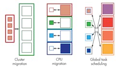
Dealing with run modes in a single-core solution is hard enough, but the job becomes significantly more complex as more cores and cores of different characteristics are mixed together. For example, ARM’s big.LITTLE architecture pairs matching low-performance/low-power cores with high-performance/higher-power cores (see “Little Core Shares Big Core Architecture” at electronicdesign.com). Applications can be switched from one core to another since they have compatible instruction execution capabilities differing only in performance.
Switching between cores turns out to be just one of the ways big.LITTLE can operate (Fig. 4). System implementations initially employed simplistic cluster migration running all the smaller, low-power cores at the same time and shutting down the bigger, high-performance cores. Subsequent implementations allowed one of the cores in a big.LITTLE pair to run. The implementation of a global task scheduler eventually enabled all cores to be employed if that was the most efficient. Hardware accelerators often allowed a smaller, low-power core to handle jobs like multimedia streaming.
Sometimes optimizing computation while maintaining power utilization is a system requirement. This is often the case in servers where power and related heat limitations must be maintained. Intel’s Turbo Boost technology is an example of how operators can specify power limitations and permit the system to adjust the number of cores and their operating frequencies to stay within the limitations. This lets cores operate at speeds higher than the rated normal speed for some period of time.
AMD’s new Beema and Mullins chips, which target mobile devices, exploit the race-to-idle behavior (see “Platform Security Processor Protects Low Power APUs” at electronicdesign.com). AMD’s Skin Temperature Aware Power Management (STAPM) technology tracks the temperature of the system to see if its performance can be increased. The logic is that the current job can be completed sooner and the system can be put into idle mode, which uses significantly less power. This technology also operates with AMD’s Intelligent Boost Control, which will speed up a selected set of tasks based on an internal microcontroller’s observation of the system that can determine in real time which tasks are frequency sensitive.
Peripheral Pairing
Peripherals come into play with run modes, but there is more to peripheral control when it comes to power utilization. Powering down a peripheral that is not required is the simplest method of reducing system power requirements. Sometimes, a peripheral will never be used because a particular application does not need all the peripherals supplied. An off-the-shelf part that matches 100% utilization is rare even given the hundreds of SKUs that many vendors provide.
Some systems often provide multiple peripherals that provide similar functionality but with different performance and power characteristics. The Silicon Labs EFM32 series takes this approach. For example, the chips have a low-speed, low-power UART as well as a high-speed, high-power UART. The developer decides how they are used, but one scenario would have a control link via the low-power UART and data would be transferred using the high-performance UART. Typical system operation has the system in a low-power sleep mode with the low-power UART operational but waiting for a byte that will signal an incoming control packet. The UART can perform basic pattern matching, so it will only turn on the processor when the desired data is received.
The Renesas RL78’s “snooze mode” allows peripherals like the analog-to-digital converter (ADC) to operate while the processor is asleep. The system can detect when an ADC value is out of range and wake up the processor. Without this feature, the processor would have to be started each time an ADC value was obtained. This is not an issue if this is necessary most of the time. But if it is not, allowing the CPU to sleep can save considerable amounts of power.
This type of “smart” peripheral provides a wakeup scenario that is common in embedded applications. Of course, the simplest incarnation is the rising or falling transition on a single-input port, but more complex configurations are available on some systems that can link peripheral input and outputs together.
Cypress Semiconductor’s PSoC microcontroller series provides an extreme example of configurable peripherals. They not only can be linked to any pin or other peripheral, but the peripherals themselves are constructed of blocks configured to perform the desired function. It is not as extreme as an FPGA but more akin to a logic array with many specialized analog and digital functional blocks.
A more common configuration has fixed peripheral blocks but with flexible linkages between peripherals. For example, an ADC result triggered by a timer might be sent via a UART all without CPU intervention. Typically, the CPU is asleep. Vendors have different names for this type of feature.
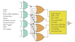
The STMicroelectronics STM32 has autonomous peripherals. Microchip’s Configurable Logic Cell (CLC) links together other interesting peripherals (Fig. 5) like a numerically controlled oscillator (see “Microcontroller Incorporates Programmable Logic” at electronicdesign.com). Silicon Labs’ EMF32 has a peripheral reflex system (PRS) that performs a similar function (see “Low Cost, Low Power 32-bit Cortex-M0+ Takes Aim At 8-bit Space” at electronicdesign.com).
Small-Scale Asymmetric Multicore
Symmetric multicore solutions are common at the high end of the compute spectrum, but single-core solutions dominate the low end. ARM’s big.LITTLE architecture is more like the symmetric designs since the cores are functionally identical.
Systems with asymmetric cores like Texas Instruments’ OMAP have been a common way to blend regular CPU cores like DSPs. They provide improved power utilization by delivering more efficient processing capabilities.
Asymmetric multiple-core solutions are becoming more common in the microcontroller space. ARM’s Cortex-M0 and Cortex-M4 is one of the more popular combinations. The Cortex-M0 handles peripheral chores while the Cortex-M4 does the heavy computational lifting.
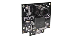
A 204-MHz NXP LPC4330, one of the Cortex-M0/M4 combinations, is found in the Pixy camera (Fig. 6). The Cortex-M0 interfaces with the camera chip and handles the initial data transformation (see “A Tale Of Two Camera Kits” at electronicdesign.com). The Cortex-M4 works on the image analysis, providing a host computer with its object recognition results.
Delivering a power-efficient solution is easier given the wide variety of features available to developers. No one system provides all combinations of hardware and software features, but most platforms have many of the optimization attributes presented here. The challenge for developers is to determine which will have the most effect on their applications and to then utilize those features in a manner that reduces power utilization while meeting application requirements.
