This file type includes high resolution graphics and schematics when applicable.
Combining wireless power with wireless connectivity makes it possible to design a completely sealed device with no external connectors. Consequently, wireless power is ideal for any portable equipment that needs to operate in outdoor or wet environments (for more on wireless-power essentials, see "Electromagnetic Induction: The Basic Principle Behind Wireless Power"). Examples include wearable devices such as smart watches or fitness bands, medical equipment (that must be washed or sterilized), or outdoor-use devices including cameras, communications equipment, or measurement instruments.
Wireless power has steadily gained popularity over the past several years. While it began as a means of improving end-user convenience in recharging mobile devices, it’s now becoming a standard feature in several new applications. As the technology finds its way into a wider range of applications, specific solutions tailored to specific power levels will be required to optimize system-level performance. Magnetic component design, critical tuning capacitors, and, of course, the silicon components used for power conversion must all be properly selected to achieve the desired results.
Today’s Leading Standards
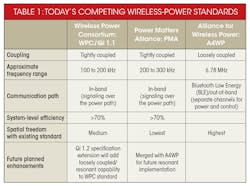
Three standards compete within the world of wireless power: the Wireless Power Consortium’s WPC, the Power Matters Alliance’s PMA, and the Alliance for Wireless Power’s A4WP (Table 1). All three employ the same basic physical principles to transmit energy. However, they use different combinations of frequency, coupling constant (K) and inductor Q factors.
WPC and PMA use high-K (lower positional freedom) and can operate with lower-Q inductors. Both WPC and PMA are relatively low-frequency compared to A4WP, which means they have higher inductance values (i.e., in the range of several microhenries).
Tightly coupled, near-field systems also have relatively high efficiency. However, they require precise placement and alignment of the receiver (battery-powered device) to the transmitter (charging pad).
A4WP is designed to operate as a loosely coupled system, so the coils needn’t be precisely aligned. The notable advantage of this system is its high positional freedom. Thanks to that freedom, the receiver (portable device) can be placed in a wider area relative to the charging surface. This provides extra convenience to the end user. Its higher frequency (6.78 MHz) allows for the design of high-Q/low-inductance values for the RX coils.
This system is technically more complex than the lower-frequency, closely coupled systems. It may grow in popularity, though, as technical challenges are resolved in the future.
Optimized Solutions for 2-, 5-, 10-W Applications
The first WPC/Qi standard, which led to broad adoption of wireless power in smartphone applications, was targeted to meet 5-W output-power capability. This power level corresponds to the typical one- to two-hour charging time common for smartphone applications (roughly 1-A charge rate into a single-cell Li-ion battery). However, as applications for wireless power become more diversified, power circuits can be optimized to match different needs.
Smartphone devices typically use batteries in the 1500- to 3000-mAH range, while batteries for common wearable devices might range from 50 to 300 mAH. Thus, wearable-device battery-charge rates (and physical sizes) are correspondingly smaller. Though wireless-power transfer efficiency is generally lower at these power levels, thermal management still can be a concern due to the small size and limited area available for heat dispersion. Conversely, newer smartphones and tablets are increasing their battery size to accommodate larger displays and higher processing-power demands.
Other applications, such as industrial handheld terminals, also may require larger batteries and higher battery voltages (e.g., two-series Li-ion packs), which require more output power.
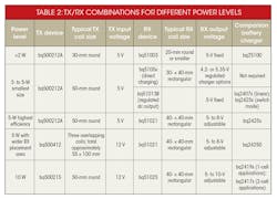
Production-ready solutions are now available and optimized for less-than-2-W, 5-W, and 10-W power-class devices. Table 2 summarizes the appropriate combination of TX and RX controllers, and magnetic component sizes.
Special Considerations for Low-Power/Wearable Applications
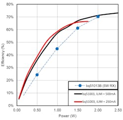
For a low-power application, total system efficiency is enhanced by using the right type of wireless power receiver. One such example is Texas Instruments’ bq51003, which is optimized for efficiency at low power (Fig. 1).
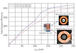
In low-power applications, small size is often a key consideration for devices such as remote sensors or wearable products. Typical 5-W, inductively coupled, wireless-power systems have TX coils in the 40- to 50-mm diameter range; RX coils fall in the same general size range (35 mm across or larger). But if the RX coil shrinks below 25 mm in diameter (typical for small wearable products), its efficiency will degrade significantly when paired with a standard TX coil, and in some cases may not start up reliably. In general, if the TX and RX coil sizes are comparable, the coupling factor (K) is optimized (Fig. 2).
Optimizing for Higher Power
To extend power capability to 10 W, several additional points must be considered. First, the silicon power components must be designed to handle the peak and continuous power levels. On the transmitter side, power-FET components are external to the transmit controller, so they can be scaled up as needed to handle peak currents. On the receiver side, where a physically small solution is important, integrated FET devices are used to provide a single-chip implementation. The FETs in the RX controller must provide lower RDS_ON (relative to the 5-W receivers) to enhance efficiency and thermal performance.
Magnetic components (TX and RX coils) must also be rated to handle higher peak currents needed for 10-W power transmission.
Finally, because the magnetic field strength will be higher for a 10-W system, the receiver-side shielding must be larger (compared to a 5-W system). This will provide better shielding for the system’s metal components, as well as minimize “friendly metal” losses on the receiver side.
Recall that in Figure 1, the RX controller provides feedback to the TX controller, asking the TX to vary its output power as needed, based on varying load conditions (plus coil alignment and coupling efficiency). There are two common approaches to varying output power: the TX coil can be excited with a constant-amplitude/variable frequency ac signal; or it can employ variable amplitude/fixed-frequency excitation.
Variable-frequency control eliminates the need for an adjustable pre-regulation stage on the TX side, and relies on the resonant tuning of the TX/RX tank circuits. When the TX operating frequency approaches the resonant point, the maximum possible power is transferred from the TX to the RX.
To reduce the power delivered to the RX side, the TX controller increases its frequency away from the resonant peak. At lighter loads (when the RX needs less power), there’s a rise in TX frequency.
However, this approach makes the power delivery/control process dependent on coil characteristics. A variable-frequency architecture may also present some challenges in controlling electromagnetic interference (EMI) when used at higher power levels.
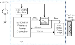
The 10-W transmitter system operates at fixed frequency, but implements an adjustable pre-regulator to vary the dc rail used for coil excitation. A full-bridge circuit generates an ac excitation for the TX coil (Fig. 3).
The 10-W wireless receiver output voltage can be adjusted with external feedback resistors across the 5- to 10-V range. This allows for charging of either one- or two-series cell configurations, and can maintain high efficiency for the one-cell case when combined with a wide-input-voltage-range, switch-mode, narrow-voltage direct-current (NVDC) type of charger. The NVDC charger architecture enables efficient charging of low-voltage batteries while reducing the input current required from a higher-voltage source (such as the wireless RX output).
Receiver Considerations
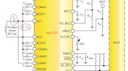
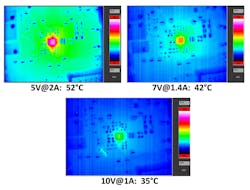
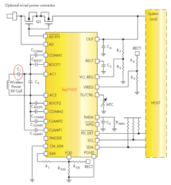
The thermal response of the receiver circuit is improved by using higher output voltage at lower current (Fig. 4). The series-resonant capacitor (C1) is also critical in terms of optimizing thermal performance (Fig. 5). In practice, multiple parallel capacitors are implemented to provide the total capacitance.
For further information on wireless-power-related devices, check out Texas Instruments' wireless-power transmitter and receiver, bq500215 and bq51025, respectively.
This file type includes high resolution graphics and schematics when applicable.
