Oscilloscope or Analyzer? Choosing the Right Instrument for Your App
This article is part of the TechXchange: Oscilloscope Techniques
This article appeared in Microwaves & RF and has been published here with permission.
Members can download this article in PDF format.
What you’ll learn:
- No instrument, whether in the time or frequency domains, is suitable for all use cases.
- Signal/spectrum analyzers shine for ensuring standards conformity.
- Oscilloscopes tend to be more versatile, especially modern ones that incorporate both time- and frequency-domain capabilities.
Modern high-end oscilloscopes contain high-speed analog-to-digital converters (ADCs), which allow them to cover frequency ranges that historically could only be investigated using a spectrum analyzer. By also integrating a high-bandwidth analog front end, modern oscilloscope architectures enable direct sampling of high-frequency signals without analog downconversion, leading to unprecedented analysis bandwidth ranges.
Some oscilloscopes in the market today have a bandwidth of up to 16 GHz and are capable of directly acquiring a nominal 8-GHz RF signal with 16-GHz bandwidth. As of now, this can’t be done with a signal and spectrum analyzer.
Spectrum analyzers, on the other hand, can cover frequency ranges up to 85 GHz and beyond, enabling them to address most applications of wireless, cellular or satellite communications, radar equipment, and IoT devices. For such apps, qualities exclusive to spectrum analyzers come to the fore. These include high dynamic range, which allows them to display very small signals in the vicinity of a strong carrier signal. Moreover, spectrum analyzers also can be used for measurements in the time domain, such as measuring the transmitter output power of time-multiplex systems as a function of time.
In this article, we will examine the differences between both instruments and the use cases, where each of them represents a best fit for the typical requirements of the corresponding measurements.
Signal and Spectrum Analyzers
A spectrum analyzer shows the signal level versus frequency at a selected resolution bandwidth. This can be employed to measure basic signal parameters, while other parameters such as the filter settings or a frequency response could be estimated from the signal shape visible on the screen. Other measurements include signal-to-noise ratio (SNR) and the detection of spurious emissions, which may need to be measured over a large frequency range.
In swept-spectrum mode, the analyzer only regards a small part of the spectrum at a time. This frequency selectivity is the key to the analyzer’s high dynamic range and lets the instrument measure and display the entire spectrum from 2 Hz to 85 GHz in a single measurement. With external mixers, the displayable frequency range can be expanded by hundreds of gigahertz.
A spectrum analyzer is usually chosen when spectrum measurements are required to ensure conformity with standards and regulations. In mobile radio, for example, these include spurious emissions, adjacent-channel leakage ratio (ACLR), and spectrum emission masks (SEM).
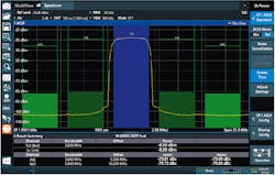
While SEM measurements are concerned with single spurs, ACLR analysis (Fig. 1) involves assessing the integrated power over frequency of the neighboring channels of a communications signal. Both require measuring very small levels in the immediate vicinity of a strong signal, hence benefiting from the spectrum analyzer’s dynamic range and frequency selectivity.
Spectrum analyzers also are typically preferred for measuring electromagnetic interference (EMI) during pre-compliance testing. The respective EMI standards require a minimum of spurs to be measured with the appropriate EMI detectors (quasi-peak, CISPR-Average and RMS-Average (CISPR-RMS)).
Digital Signal Analysis
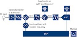
Many of today’s spectrum analyzers can handle digital signals, too. An input signal bandwidth up to 1 GHz is common, while some instruments have bandwidth up to 8.3 GHz. The analyzer’s front end (Fig. 2) mixes the signal to a low intermediate frequency (IF) before sampling with a wide-bandwidth ADC and then digitally downconverting into the baseband to be equalized. The resulting digital I/Q values contain all signal information within the bandwidth and dynamic range.
The signal can then be further processed using appropriate application-specific measurements. These may be available on the device or via PC software like Rohde & Schwarz’s Vector Signal Explorer (VSE).
Thus, the analyzer is used when working with communication systems to measure, for example, important signal parameters such as error vector magnitude (EVM), I/Q offset or imbalance, and the level ratio of pilot to data channels. In radar applications, it’s able to help with measurements of interest, including the phase, frequency, modulation, and level of pulsed signals over the pulse duration.
Analyzers can perform various other measurements at component, module, and device level, particularly when used with an appropriate measurement application. These include the noise figure and gain of amplifiers and the phase noise of oscillators. With these instruments, one may make very precise measurements, almost down to the thermal noise floor.
Some high-end instruments also can perform measurements such as uninterrupted real-time spectrum analysis and uninterrupted streaming of digital I/Q data.
RF Testing with Oscilloscopes
With their large analysis bandwidth, today’s leading oscilloscopes can address a wide variety of applications such as radar. Radar range resolution is a key parameter and is directly proportional to the available bandwidth. In other applications, although the signal of interest may have a relatively narrow bandwidth, the oscilloscope can measure out-of-band signals such as harmonics, neighboring channels, and interfering signals.
On the other hand, a high analysis bandwidth can call for extra care when acquiring narrowband signals. Consider a 2-MHz-wide Bluetooth Low Energy (BLE) signal at a center frequency of 2.4 GHz. Acquiring the signal of interest may be relatively easy. However, unless filters are applied, all possible interference signals from dc up to the oscilloscope’s maximum frequency also will be acquired. With some high-end oscilloscopes, users can constrain the analysis window to the signal of interest by designing digital filters with software tools and importing the filter coefficients.
Although applying an appropriate digital filter improves the SNR, the question arises whether the achievable capture time can still be improved for such a narrowband signal. Even if the sample rate is reduced to the minimum stated by the Nyquist theorem, the capture time for the BLE signal in the previous example is less than one second. Digital downconversion, available on some high-end oscilloscopes, allows the time to extend to about 500 seconds.
Advanced Trigger Systems
Oscilloscopes are typically equipped with a much more advanced trigger system than signal and spectrum analyzers. This enables a very accurate detection of short, intermittent, burst, or pulse signals. It’s a significant advantage in radar applications, in which a precise detection of a pulse/chirp start is essential.
Whereas oscilloscopes with a conventional analog trigger will split the signal into two paths, instruments from Rohde & Schwarz provide a fully digital trigger system that operates directly on the samples of the ADC. This results in a lower trigger jitter and a flexible trigger sensitivity. Moreover, all trigger types support the full bandwidth of the oscilloscope.
Phase-Coherent Multichannel Analysis
For various reasons, multi-antenna designs have become essential in a range of wireless applications. In radar, for example, multi-antenna systems are state-of-the-art for estimating the angle of arrival (AoA) —the direction from which the surrounding objects are coming—based on the phase difference between multiple receive paths.
Test equipment needs multichannel capabilities to characterize these types of systems and ensure that all channels are constantly phase coherent. Oscilloscopes typically provide multiple tightly aligned channels. Unlike spectrum analyzers, they require no additional enhancements such as time-base and local-oscillator (LO) sharing to perform phase-coherent measurements. Hence, they’re a cost-effective and easy-to-use solution for testing multi-antenna systems.
When testing equipment using frequency ranges beyond the oscilloscope’s maximum bandwidth—e.g., automotive radar in the 77-to 81-GHz range, or the new 60-GHz radar for gesture sensing—signal acquisition is accomplished using external mixers. An oscilloscope that supports real-time de-embedding can compensate for the losses induced by the additional components in the signal path. While tools for basic analysis in the time and frequency domains are often built-in (Fig. 3), a dedicated tool such as R&S’s VSE software may be needed for a more in-depth pulse and transient analysis.
Similarly, 5G NR communications rely on multiple antennas with beamforming to transmit the signal in a desired direction. This is accomplished by generating a defined phase shift of each adjacent input signal stream, which must be kept constant to ensure the generated beam stably points in the wanted direction.
An oscilloscope like the R&S RTP, with its multichannel input, allows a phase-coherent measurement of up to four input streams. Therefore, it can handle multiple 5G NR input channels. With the R&S VSE, it’s able to perform a wide range of measurements, including MIMO-specific measurements like the phase difference between the input signals to characterize the beams when testing the transmitters of 5G NR base stations or small cells.
System-Level Debugging
Whereas signal and spectrum analyzers are dedicated instruments for RF signal analysis, oscilloscopes are general-purpose instruments that allow for multiple measurements besides the acquisition of RF signals. Various options are available for bus triggering and decoding, as well as power and time- and frequency-domain measurement.
The consistent time alignment between all of those measurements can help users correlate acquired RF signals with other signals, such as the supply voltage or digital bus signals. An example may be simultaneously acquiring CAN or Ethernet signals together with radar signals when developing and debugging automotive radar modules.
FFT and Zone Trigger
Most state-of-the-art oscilloscopes provide fast-Fourier-transform (FFT) capabilities, which enable correlation to the time domain. With the UWB 802.15.4z standard gaining traction in automotive applications, for example, the FFT capability makes it possible to simultaneously examine the ultra-wideband (UWB) signal in both the time and frequency domains.
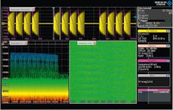
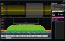
Using the gated FFT feature provided by R&S oscilloscopes, engineers can define a signal portion in the time domain and plot the spectrum of this specific portion. One may also make spectral measurements such as the channel power and the occupied bandwidth (Fig. 4).
In addition, when combined with a dedicated near-field probe, the FFT and trigger capabilities are useful for investigating EMI in electronic designs.
Some high-end oscilloscopes also provide a zone trigger, which is useful for EMI debugging purposes as well. Often, multiple zones can be graphically defined in the time and frequency domain and combined through logical operators to help investigate conditions such as fading effects on a WLAN signal caused by short or intermittent interference, which are otherwise hard to track down.
Summary
The main advantages of signal and spectrum analyzers result from the frequency selectivity. These include the high dynamic range, which allows low-level signals to be analyzed in the vicinity of a strong signal. Standard-compliant ACLR and SEM measurements are usually only possible with a spectrum analyzer.
With signal demodulation, an analyzer can deliver significantly better results, such as EVM values, particularly for signals with a large bandwidth and a high crest factor. Other advantages include the high maximum input frequency and continuous sweep from minimum to maximum frequency, as well as very long, seamless recording times, depending on the bandwidth. Moreover, analyzers are usually preferred when measuring phase noise and noise figure/gain, and for real-time spectrum analysis.
The main advantages of an oscilloscope result from the superior analysis bandwidth and full signal capture, including dc components, as well as the availability of several (typically two or four) phase-coherent inputs. Typically, an oscilloscope is preferred for wideband measurement of signals in the analog baseband, phase-coherent measurements of several sources, and time-correlated multi-domain measurements.
About the Author
Ezer Bennour
Product Manager Signal and Spectrum Analyzers, Rohde & Schwarz
Ezer Bennour is a product manager for signal and spectrum analysis at Rohde & Schwarz. In a previous position, Bennour focused on exploring RF application fields for high-end oscilloscopes. Before joining Rohde & Schwarz in 2019, he gained experience as an application engineer with a special focus on modular RF instruments. Ezer holds a diploma in electrical engineering and information technology from the University of Stuttgart in Germany.
