Reduce Noise by Synchronizing Switching Regulators
This article is part of the TechXchange: Delving into EMI, EMC and Noise
Members can download this article in PDF format.
What you'll learn:
- How to deal with radiated/conducted emissions with synchronized regulators.
- Why adding clock signal generator is important for a successful solution.
Most of today’s electronic circuits require multiple supply voltages. Twenty years ago, a general-purpose 5-V supply voltage was sufficient for TTL logic and everything else in a system. Today, for example, 2.5 V is needed for the input/output (I/O) of a microcontroller, 0.9 V for the core, and 3.3 V for a sensor. Different voltages also are required for interfaces, e.g., 5 V for USB.
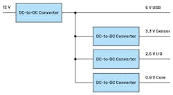
To achieve maximum energy efficiency these days, switching regulators are used for individual dc-dc conversion stages. Figure 1 shows a typical power-conversion architecture.
If various switching regulators with different switching frequencies are operating in a system, you will see each respective fundamental frequency and its harmonics in the frequency spectrum. In addition, you’ll see the beat frequencies that correspond to the differences between the frequencies of the various switching regulators.
This problem of generated radiated emissions as well as conducted emissions at the inputs of the switching regulators can be alleviated by synchronizing the various switching regulators in the system. Many dc-dc converter ICs have SYNC pins to which a clock signal can be applied. With an internal phase-locked loop (PLL), the switching frequency of each dc-dc converter sets itself to this supplied frequency.
Clock-Signal Generation
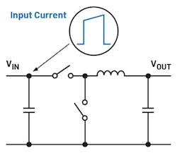
That’s an elegant solution, but how is this clock signal generated? Because buck converters cause input-side pulsed currents, it makes sense to ensure that they do not all draw current from the input source at the same time (Fig. 2). A phase-shifted external SYNC clock signal provides a remedy here. It greatly reduces the conducted emissions at the input side of the switching regulators.
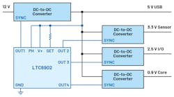
The LTC6902 is a small additional clock generator device for controlling the SYNC pins of multiple switching regulators in a system. It’s one of the useful tools in a power-supply developer’s toolbox.
This clocking device can provide a clock signal between 100 kHz and 20 MHz, and drive the SYNC pins of up to four switching regulators separately with a certain phase shift. Furthermore, if required, it even uses the optional spread-spectrum frequency modulation (SSFM) to lower individual peaks in the frequency domain. In some applications, this trick makes it possible to reach different EMC specifications.
Figure 3 shows the power-supply architecture from Figure 1 with the LTC6902 multiphase oscillator. It’s supplied with a voltage of 5 V. This voltage is generated by a buck converter that converts 12 V to 5 V. Typically, it’s not problematic for switching regulators if they first independently start up with their own internal oscillators and are then supplied with an external clock. Details can be found in the datasheets for the respective switching regulators.
In addition to the LTC6902 four-phase part, there’s the LTC6908, a two-phase device, and the LTC6909, an eight-phase device.
A low-noise system design also is possible if there are multiple switching regulators on one board. Apart from the usual optimizations—for example, selection of appropriate switching-regulator ICs, optimization of the board layout, and addition of various filters—the use of an extra clocking module can be beneficial, too.
Read more articles in the TechXchange: Delving into EMI, EMC and Noise


