Essentials for Effective Protection Against Overvoltage Events
Members can download this article in PDF format.
What you’ll learn:
- Determining the optimal overvoltage circuit protection strategy based on the “Three Ds” of device functionality.
- A better understanding of voltage-switching vs. voltage-clamping technologies.
- Why device core materials and technologies matter in selecting an overvoltage protection solution.
Potentially damaging electrical overvoltage threats are an everyday occurrence in today’s electrical and electronic world. Their intensity ranges from very light electrostatic-discharge (ESD) events to very intense lightning strike-induced surges on data lines and power lines. These events have the potential to lock up microprocessors, damage sensors, cripple computer communications ports, cause severe damage to equipment, and even threaten harm to users through electrical shock or cause a fire.
To address this wide range of threats, an equally wide range of circuit protection technologies is available. Currently available components span from small, fast PCB-mounted components to large, rugged wall-mounted devices. Some of these devices are binary in nature—they switch on or off. Others are more proportional or linear in their response to events.
Specifying circuit protection components is a bit like buying insurance. You need adequate coverage to prevent damage, but no one wants to overpay for insurance they will likely never need.
Because of the broad selection of circuit protection technologies and components available, it’s helpful first to categorize the action that an overvoltage protection component takes to mitigate damage. Overvoltage protection devices are placed across the line being protected. The response to an overvoltage event can be classified into one of the “3Ds”:
1. Divert excess energy to ground: Often referred to as “voltage switches,” these devices switch their impedance to a very low level once their terminal voltage reaches a threshold value chosen by the designer, sending the excess current to ground.
2. Dissipate excess energy: Regularly known as “voltage clamps,” these devices lower their impedance across the protected line to attempt to limit or regulate the voltage to a level chosen by the designer.
3. Disconnect the load from the line: This unique technology attempts to open like a fuse and limit or block current flow when the line voltage exceeds a value chosen by the designer.
Voltage Switches
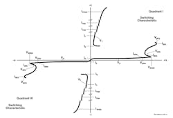
Voltage switches have very high resistance when the voltage across them is below their threshold voltage (Fig. 1). Once their voltage threshold is exceeded, they transition to very low resistance, diverting the fault current to ground.
Voltage switches are binary devices—they’re either “on” or “off.” In the “off” state, they have voltage across them, but very little leakage current. In the “on” state, they have large currents, but low terminal voltages. This way they dissipate very little power, which means they can be much smaller devices than similarly rated voltage clamps.
However, not all circuits can tolerate being shorted out by a voltage switch. If installed on an ac power line, the voltage switch could cause a fuse to blow or breaker to trip every time it was triggered. Also, to reset the voltage switch to the high resistance state, the current through the device must be interrupted—or at least fall below the specified “holding current.”
Due to these limitations caused by this “latching on” action, voltage switches are usually found only on data lines or lines with limited power capability, such as those used in telecom or HVAC signaling.
Gas discharge tubes (GDTs) are voltage switches made from ceramic and metal materials. These are formed as an enclosed gap between two metal electrodes in a controlled atmosphere. Such ceramic devices are very rugged and relatively inexpensive. They have very low capacitance, making them ideal for high-speed data lines—especially those exposed to areas where lightning-induced surges can be very strong.
Thyristor protection devices are unidirectional or bidirectional 4-layer (PNPN) silicon structures. They switch faster than GDT devices but exhibit higher capacitance and lower surge ratings. Thyristors are often used to protect data ports, sensitive sensors, and other delicate interfaces.
For ESD protection, many suppliers offer voltage-switching silicon punch-through diodes and air-gap devices.
Voltage Clamps
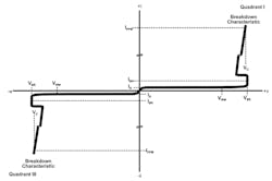
Voltage clamps also exhibit very high resistance at voltages below their “threshold” voltage (Fig. 2). Once the voltage across the clamp rises above this threshold, the current begins to increase rapidly—as their resistance decreases.
Metal-oxide varistors (MOVs) are bidirectional voltage clamps fabricated from sintered ceramics based on zinc oxide. They come in two basic structures: leaded and surface-mount devices.
Leaded devices are typically formed into discs with leads attached to each metallized side and covered in an epoxy powder coat. Surface-mount devices, made in thin layers of ceramic “tape,” are commonly referred to as multi-layer varistor (MLV) devices. MLV devices are typically used in low-voltage signal applications, while leaded MOVs are often used in ac power protection.
Moreover, suppliers are developing new hybrid protection devices that combine an MOV and GDT.
MOV devices are known to have inherent weaknesses. Constant exposure to ac line voltages and seemingly insignificant line noise can increase the MOV’s leakage current over a long period of time. With increasing leakage current, the MOV begins to dissipate continuous power, which warms the device and further increases the leakage current. This can lead to a thermal runaway condition, resulting in MOV failure.
The GDT in a hybrid protection device effectively removes the MOV from the line voltage. When a surge event occurs, the GDT reconnects the MOV to the line in less than a microsecond. Once the surge event is over, the GDT disconnects the MOV from the line. This means the MOV is connected to the ac line only when it’s needed.
Another type of hybrid protection device is constructed by forming the MOV from two specially shaped thin discs, whereby the GDT function is performed by a gap between the two discs. This type of hybrid device is able to better manage the surge current, handling twice the surge current as an MOV of the same diameter. Because it’s not constructed with an external GDT, it features the same thickness as the MOV, providing a significant space-saving advantage.
Both hybrid protection solutions also drastically lower the capacitance when compared to an MOV alone. Thus, they’re ideal for use on lines where high-speed data is present.
Silicon-based voltage clamps can be either unidirectional or bidirectional. They’re available in multiple sizes to handle surges from tiny ESD pulses to near-direct lightning strikes of 10 kA or more. Such clamps include transient voltage suppressors (TVS), power TVS (PTVS), silicon avalanche diodes (SAD), and Zener diodes.
The breakdown voltages of silicon devices can be more precisely controlled than with ceramic devices. Their breakdown voltage also is more stable over time, making them a premium choice for very sensitive applications.
In their active state, voltage clamps conduct current while maintaining a high voltage across the line. This leads to very high levels of power dissipation. To handle these high-power levels, voltage clamps tend to be larger per their increased surge and voltage ratings.
Electronic Current Limiters
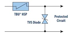
Combining two technologies, electronic current limiters (ECL) are a form of blocking device that uses a small TVS diode to sense the overvoltage event and trip an ECL such as a Bourns Transient Blocking Unit (TBU) High-Speed Protector (HSP) (Figs. 3 and 4).
ECL devices are FET-based two-terminal integrated circuits that sense their current and react in about a microsecond to currents that exceed their rated trip current. Once tripped, the internal FET devices are held in the off state using a small quiescent current (~1 mA) until the fault is removed. Once the fault is cleared, the ECL will return to its normal low-resistance state.
In this arrangement, the TVS device begins to conduct when the threshold voltage is exceeded. This causes current to flow in the TVS device, which in turn trips the device. This action disconnects the protected circuit from the overvoltage source. Because the ECL limits the current through the TVS device, the maximum voltage let through to the protected circuit is fixed no matter the size of the incoming surge event.
Continued Design Protection
Keeping our electrified world working in the face of overvoltage threats from lightning, induced surges, utility power voltage-regulation problems, or even just ESD is the mission for overvoltage protection devices (see table).
There’s a lot to be considered when designing effective protection circuitry. Nonetheless, careful selection and appropriate testing helps to mitigate the risk of overvoltage threats, thereby increasing the reliability and uptime in today’s modern electronic equipment designs.


