Easy Galvanic Isolation
Members can download this article in PDF format.
What you'll learn:
- Using the flyback-converter topology with a transformer for galvanic isolation.
- What is the no-opto converter topology?
- What is the iso-buck converter alternative?
Many electronic circuits require galvanic isolation, which typically involves the use of transformers. Numerous different topologies are employed to transmit electrical energy via a transformer. One widely used circuit type, especially for low power of approximately 50 W or less, is the flyback converter.
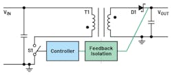
Figure 1 shows a schematic of a simple flyback converter. While switch S1 is on, a flyback converter stores energy in the transformer core T1. When S1 is off, the energy stored in the core is released to the output through the secondary winding of T1 through the free-wheeling diode D1.
It can be seen in Figure 1 that besides the power path, the feedback path (shown in green) is required. It’s used to precisely regulate the output voltage. Unfortunately, this feedback path is quite complicated because here, too, the feedback signal must be transmitted through a galvanic isolator. Thus, optocouplers or digital isolator modules such as ADuM3190 are utilized. The feedback signal also can be sensed on the primary side, in which case no galvanic isolation of the feedback path is needed.
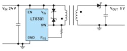
A galvanically isolated flyback circuit with a small footprint can easily be built using a converter from the no-opto product platform offered by Analog Devices. Figure 2 shows an LT8301 with an input voltage of up to 42 V and a maximum switch current of 1.2 A.
As is evidenced in Figure 2, no feedback path from the output voltage back to the primary-side switching regulator can be seen. However, there’s a hidden internal feedback path via the transformer. During the off time of the primary-side switch, a voltage that’s reflected back through the primary winding of the transformer is measured. This allows for precise information on the status of the output voltage to be obtained on the primary side.
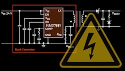
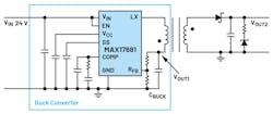
Besides this galvanically isolated solution, there’s another clever way to build a galvanically isolated flyback circuit. This technology is known as an iso-buck converter (Fig. 3).
The main difference between a general flyback converter and an iso-buck converter is the capacitor (CBUCK) between the primary-side transformer winding and ground. In the MAX17681, the primary-side winding of the transformer is driven with a half bridge. This means that the MAX17681 has a high-side and a low-side switch. In a no-opto flyback (Fig. 2), there’s just one switch, which is between the primary-side winding of the transformer and ground.
The iso-buck can be thought of as a simple buck converter with a coupled inductor and thus a generated, isolated voltage. The blue line in Figure 3 delineates the buck converter. The voltage at CBUCK corresponds to the regulated voltage of this integrated buck converter.
Neither of these galvanically isolated switching-regulator concepts requires signal feedback with an optocoupler. What are the advantages of each solution?
The no-opto converter (Fig. 2) doesn’t require a large primary-side bypass capacitor (CBUCK) and is driven internally with one switch. The advantage of an iso-buck converter is that it also has a precisely regulated primary-side voltage available. This can also be used in the system, for example, to supply the electronics of primary-side circuit devices with energy. It must be set in such a way that when an available transformer with the corresponding turns ratio is used, the desired galvanically isolated voltage VOUT2 is generated.


