This file type includes high resolution graphics and schematics when applicable.
Use of electromagnetic induction for cooking purposes is witnessing widespread uptake around the globe. The market for induction-based hobs is set to progress at a compound annual growth rate (CAGR) of 6.83% between now and 2018 (according to industry-analyst firm TechNavio). However, the way that induction cooking is being implemented varies quite significantly, with different regions following their own unique path. In this article, we will look at the equivalent circuits for quasi-resonant cookers and coil characteristics relating to the various pan materials employed.
Several circuit topologies are used for induction cooking, with each finding favor in particular parts of the world. In Europe, multi-element, half-bridge resonant cooktops are becoming more commonplace. The Asian market is different. For instance, millions of single-element, quasi-resonant cook pads are sold each year to Chinese consumers, while rice cookers employing quasi-resonant inductance topologies have witnessed considerable traction in South Korea.
Quasi-Resonant
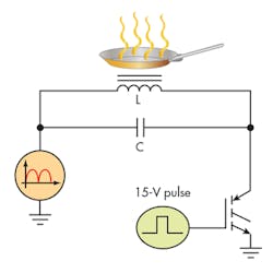
Single-element cook-pad or rice-cooker circuits typically utilize a quasi-resonant boost circuit (Fig. 1). Circuits of this kind have relatively low component counts. They often rely on a 1200- or 1350-V IGBT and can connect to a 120- or 240-V ac line that’s been rectified and filtered. The RLC tank circuit is connected to the rectified ac input and switched by the IGBT.
The preferred mode of operation involves the IGBT turning on and storing energy in the inductor and capacitor. When it turns off, the circuit resonates and the voltage increases above the input level in a sinusoidal manner. When the voltage rings to ground, the switch turns back on and again stores energy.
While the inductor and capacitor parts of the RLC structure are obvious in this schematic, the resistor is not so apparent. The pan acts as both a magnetic core and a resistance to the inductor, thus creating the load (or damping) resistance. Without a pan, the voltage will ring quite high, since it’s a very high Q circuit. This can potentially damage the IGBT. Induction cookers will have protection circuitry incorporated to guard against the “no pan” condition.
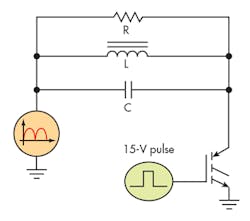
The equivalent circuit with the pan in place is detailed in Figure 2. If we consider the resistance that the pan constitutes to be the core loss of the circuit, it will be in parallel with both LC components. Some sources, however, will show it in series with the inductor.
This conversion can be made for an ac analysis, but it will not pass as a dc equivalent circuit. That’s because the inductor resistance is typically in milliohms, and adding 20 ⦠to 100 Ω in series would clearly change this substantially. Nevertheless, many simulations use such series equivalents (revealed in the graphs below).
The damping resistance R seen in the equivalent circuit consists of a combination of two different loss mechanisms. The first stems from the eddy currents, which are intrinsic to any electrically conductive material. The second is when a magnetic material is used for the pan’s construction, because hysteresis losses must be considered. Currently, the majority of induction cookers solely use magnetic pans. However, development work is now underway on circuits that are suitable for non-magnetic pans.
The Role of Eddy Currents
Eddy currents are circular currents induced within electrical conductors caused by the application of a varying magnetic field. The principle behind it comes from the Law of Induction set down by Faraday nearly 200 years ago. It states that any change in magnetic-field density around a conductive coil will generate a voltage within the coil.
Changes to the magnetic field adjacent to the pan will create small voltages inside it and, due to the low resistance of the pan, a current will flow through the metal. This will subsequently be turned into thermal energy, which heats the food placed in the pan.
Eddy currents will occur in any conductor regardless of its magnetic properties. These currents are concentrated near the conductive surface and decrease exponentially with distance from this surface, which is referred to as the skin effect. The skin depth can be calculated by the equation:
where δ is the skin depth (measured in inches); µ (permeability) = 1.257 × 10⁻⁶H/m, and σ is the electrical conductivity.
The design of most pans means that they’re significantly thicker that the skin depth. Two of the most widely used alloys of stainless steel for induction cook pans are 430 and 304.
For alloy 430, the resistivity (rho) is 2.6 × 10⁶ (1/Ωm). This means that the skin depth is:
Meanwhile, the value of rho for alloy 304 is 1.45 × 10⁶ (1/Ωm). So the resultant skin depth is:
Role of Hysteresis Losses in Induction Cooking
Hysteresis losses occur in all materials with a permeability greater than air. Most induction cookers require magnetic pans as the increased losses improve the overall performance of the cooker. When the magnetic field applied to a magnetic material is increased and then decreased to its original value, the resulting field within the material fails to return to its original level in a corresponding manner. This difference is the hysteresis loss.
Hysteresis losses result in the generation of heat due to the realignment of magnetic domains. Such losses vary directly with the frequency of the flux field and as the nth power of the flux density. The relationship is described in the following equation:
Bh = Kh â f â Bmaxn
where Bh is the hysteresis loss (W/unit mass); f is the flux frequency (Hz); Bmax is the maximum flux value (Gauss); Kh is the hysteresis constant (which varies with pan material); and n is the Steinmetz exponent (which again varies with pan material).
Coil Characteristics
Induction cookers typically use either a quasi-resonant power stage or a half-bridge resonant circuit. Regardless of the circuit, the coil characteristics are the same. A high-frequency, high-current pulse is applied to the coil, which generates a high magnetic field that’s then absorbed by the pan and converted into heat.
As already explained, the pan acts as a damping resistance to the LC circuit. While it’s possible to measure the L and the C values, the final circuit is much more complicated. The pan acts as a core to the inductor coil and thereby changes its parameters.
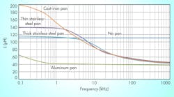
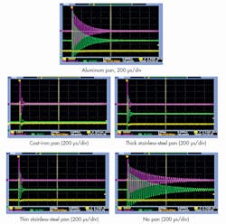
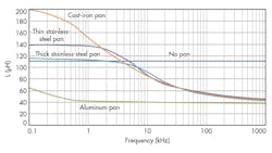
The test data compiled in Figure 3 shows the effects of various pan materials on a standard 110-µH coil used in quasi-resonant circuits. The measured inductance and resistance are greatly impacted by the characteristics of the pan material that’s placed on the cooking surface. The resistance in these measurements was taken as a series resistance and can be used effectively for an ac model.
The waveforms show the damping effect of different pan materials. In the separate screenshots, the differences in damping between no pan, magnetic pans (cast iron and stainless steel), and non-magnetic pans (aluminum) can clearly be seen.
A graph was derived from the waveforms (Fig. 4) that shows the change in inductance and losses for each of these same pans over frequency.
Non-Magnetic vs. Magnetic
As we have seen, two primary effects cause heating in induction vessels. Non-magnetic pans can be heated strictly from eddy-current losses, but, as a result, they don’t incur the heat losses possible with magnetic pans. In contrast, magnetic pans have the benefit of utilizing both eddy-current losses and magnetic-hysteresis losses. Thus, they’re markedly more effective for induction-cooking applications.
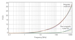
This point is made very clear in the resistance curves shown in Figure 5. The curves for the magnetic pans are very close to each other and are all distinctly set apart from the curve for the non-magnetic material. Furthermore, the impedance (both real and reactive) of the coil varies greatly with the pan material and with the driving frequency of the power circuit.
Dominic Li is a Senior Application Engineer at ON Semiconductor.
