Inject More Voltage, Power into AC Motor Drives for Industrial Robots
Download this article in PDF format.
Greater use of robots in the world of automation is bringing about higher productivity in manufacturing, as well as lowering costs. To meet those objectives, robots must have faster response times as well as higher precision in positioning—and that means improvements in motor-drive control.
Motors inside the robot supply variable speed and torque at precise points. The robot’s controller coordinates the motion along different axes for exact positioning. These movements must be done with great power efficiency.
Two three-phase motor-driver inverter designs have surfaced that can produce the required level of performance. These designs consist of high-end power supplies, intelligent motor drivers, high-performance control signal processing, and intelligent sensing that all function together to deliver the precise speed and torque needed instantaneously by robots.
Motor Control with AC Drives
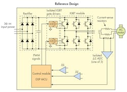
The larger industrial-strength robots utilize three-phase ac motors to move its joints. These motors require special driving circuitry to deliver the precise control necessary for precision real-time operation. The figure shows one example.
The drive electronics usually consists of a high-voltage ac-dc supply incorporating a three-phase rectifier that delivers dc to a pulse-width-modulated (PWM) inverter usually made up of IGBTs. The IGBTs deliver pulses to the three motor windings to produce the desired drive frequency.
The control derives from the feedback and processing subsystem. The feedback signals are the motor-winding currents. The voltages developed across resistors in series with the motor windings are digitized and sent to a digital signal processor (DSP), either a microcontroller or FPGA. This processor produces the PWM signals that drive the IGBTs. Isolation circuits keep the feedback signals separated from the processor circuitry and the processor separated from the IGBT gate drivers.
This simplified diagram is representative of a SMPS reference design used for high-precision, three-phase ac motor control in robots. It consists of an input rectifier to generate the high-voltage dc, isolated IGBT gate drivers—the PWM-controlled IGBTs that operate the motor. Current-sense signals from the motor phase windings are digitized by isolated delta-sigma (ΔΣ) modulators that provide inputs to the high-speed DSP that produces the PWM signals.
All of this circuitry is critical because of the high voltages and high switching frequencies involved. One improvement is the substitution of GaN FETs for the IGBTs to drive the motor windings. GaN FETs switch faster and offer less on-resistance. thereby greatly improving overall operating efficiency even when operating at high switching rates.
Other critical components are the feedback digitizers. These are isolated delta-sigma modulators that generate a Manchester-encoded data and clock signal based on the motor-winding currents.
To make it all work, the delta-sigma modulator outputs are sent to a fast DSP that runs the algorithms. These, in turn, generate the PWM signals that ultimately control the motor.
Reference Designs Aid Development
Next-generation robots would be impossible to operate without precise motor-drive control. Advances in electronics make precise control possible during real-time operation. The challenge is accumulating all of the critical components necessary to build a high-voltage, high-frequency switch-mode power supply (SMPS) that will deliver that precision control.
One solution that speeds up and simplifies the design is a reference design that specifies all of the critical components—specifically, Texas Instruments’ TIDA-00914.
This reinforced isolated phase-current-sense reference design allows designers to create a highly accurate, three-phase inverter subsystem using isolated IGBT gate drivers and isolated current/voltage sensors. It uses AMC1306E25 delta-sigma modulators that generate Manchester-encoded data/clock signals for the processor. In addition to developing a signal for each motor phase current, additional modulators are used to produce a temperature-monitoring signal as well as a signal to monitor the dc input bus.
The feedback signals are processed by the TMS320F2837x Delfino 32-bit floating-point MCU. The MCU then generates the PWM for the ISO53xxx IGBT gate drivers.
Another reference design solution is the TIDA-00915, a three-phase, high-frequency PWM frequency GaN inverter reference design for 200-V ac servo drives. It features the LMG3410 600-V, 12-A GaN power module in place of the IGBT module. The GaN devices switch 5X faster than silicon FETs, while achieving efficiency levels greater than 98% at 100 kHz and greater than 99% at a 24 kHz PWM frequency.
With GaN, designers can optimize switch performance to reduce power loss in the motor and downsize the heat sink to save board space. Operating the inverter at 100 kHz significantly helps improve torque ripple when used with low-inductance motors.
About the Author

Lou Frenzel
Technical Contributing Editor
Lou Frenzel is a Contributing Technology Editor for Electronic Design Magazine where he writes articles and the blog Communique and other online material on the wireless, networking, and communications sectors. Lou interviews executives and engineers, attends conferences, and researches multiple areas. Lou has been writing in some capacity for ED since 2000.
Lou has 25+ years experience in the electronics industry as an engineer and manager. He has held VP level positions with Heathkit, McGraw Hill, and has 9 years of college teaching experience. Lou holds a bachelor’s degree from the University of Houston and a master’s degree from the University of Maryland. He is author of 28 books on computer and electronic subjects and lives in Bulverde, TX with his wife Joan. His website is www.loufrenzel.com.

