Use Bode Plots to Meet Dynamic-Control-Behavior Requirements (.PDF Download)
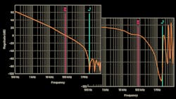
This article will describe how Bode plots can be leveraged as a tool to quickly assess if your power-supply design will meet the requirements for dynamic control behavior. Power supplies normally maintain a fixed output voltage via a control loop. This control loop may be stable or unstable. It also can regulate rapidly or slowly. In most cases, the control loop can be described via a Bode plot. With it, you’re able to immediately see the speed of the control loop and especially the stability of its regulation.
Figure 1 shows a typical switching regulator with a step-down (buck) topology. It converts a higher input voltage to a lower output voltage. The goal is to regulate the output voltage (VOUT) as precisely as possible. For this, a control loop is integrated into the circuit through the feedback (FB) pin. It detects voltage changes at VOUT.
