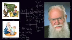
To circumvent the noise-testing problems discussed in my last column, I decided to build up my own test fixture for measuring transistor base-current noise. First I made up a schematic (figure is missing). As a sanity check, I showed it to a bunch of people. One guy did spot that I was violating the common-mode (CM) range of the LM627 main amplifier. So I told him thank you and added a couple of 1N914 diodes to bring the common-mode range down to a legal level. (I could have bluffed and told him I made that mistake on purpose, to see if anybody was paying attention, but I figured that this wasn’t the right time to play that game, as it wasn’t true….)
People asked me, “Aren’t you going to run it on batteries? You need low-noise supplies to see a low noise, don’t you?” Answer, no. Modern power supplies are pretty quiet, and this balanced (differential) amplifier (Q1A and Q1B) doesn’t need any more help than that. Also, it has a pretty good power-supply rejection ratio (PSRR).
Then they said, “Aren’t you going to put the fixture in a big sealed box?” No, that’s no necessary. In fact, usually I just run it out in the open, without even a cover, right on my bench.
Usually, I do have to turn off the soldering iron to get decent results. I also have to move it away from various instruments whose power supplies spray flux all around. The first thing I did with this fixture was add a label that said you have to monitor the dc output level. That’s to ensure that if the output pegs (hits the supply rail), you don’t want to believe the output noise levels. The next disclaimer I added stated that the bandwidth is indeterminate and depends on the layout—even a fraction of a picofarad of stray capacitance has major effects.
We fired it up and it gave us pretty reasonable data. It told us that the transistors’ base current noise was down around the theoretical levels, at least above 100 Hz. We’ve been too busy recently to devote time to getting the spectrum analyzer running down at 10 Hz, but that can wait. Then we checked on the high end of the frequency range. I started out with a feedback capacitor (CF) made out of about 2 inches of twisted pair (around 2 pF) and unwound it.
As the capacitance decreased, the bandwidth got up above 10 kHz, up toward 20 kHz. That means our feedback capacitor is less than 1/3 pF. We worked to get that because we built the feedback resistor out of three 3.32-MΩ resistors, so their inherent capacitances would be put in series and thus decreased. Also, we built “walls” out of copper-clad pc board to prevent any stray capacitance between the output and input. Heck, the output can’t even SEE the input. To connect a 0.5-pF capacitor from the output to the input, we require it to climb over one of those walls.
We haven’t used the 50-MΩ feedback resistor yet (which is made out of five 10-MΩ resistors in series), but that approach will give us good resolution when the transistors run a mere 4 to 12 µA of emitter current. Note, this circuit is just about the same as we would use to measure the base-current (bias current) noise of any op amp. But when you do that, the stray capacitance of the socket makes it pretty hard to get less than 0.5 pF from the output to the input, especially when you’re using dual or quad amplifiers.
With an op amp, you may even have to run your test with one of the pins pulled out of the socket, for evaluation. For production, you make a pc-board layout with guarding between the pins. Refer to the LMC660 data sheet (printed after June 1990) for information on guarding techniques.
Therefore, we confirmed that it is possible to make low-noise measurements. If you’re careful, you can just build up a simple circuit with a simple amount of shielding. And you can check at all times to see if there are 60 Hz or 120 Hz or 5 MHz noises intruding into your circuit.
One thing is certain, blind trust is definitely out of place here; thinking is required at all times. We also confirmed that the transistors really were low noise. In fact, they were close to the noise floor, with fewer noisy ones than usual. So, that’s encouraging.
All for now. / Comments invited! / RAP / Robert A. Pease / Engineer
About the Author

Bob Pease
Bob obtained a BSEE from MIT in 1961 and was a staff scientist at National Semiconductor Corp., Santa Clara, CA, for many years. He was a well known and long time contributing editor to Electronic Design.
We also have a number of PDF eBooks by Bob that members can download from the Electronic Design Members Library.
