EDA Vendors Should Improve The Runtime Performance Of Path-Based Analysis
This file type includes high resolution graphics and schematics.
The first time I signed off a design for fabrication, I was a physical design lead working for an ASIC vendor. My company had a very formal process for release. We sat down in a room with several pages of assorted checklists. As the engineer who had personally performed the static timing analysis of the design, I felt the heavy burden of signing off the section of the checklist labeled “timing analysis complete.”
At the time, mask set costs were in the range of a couple of hundred thousand dollars. While my sweaty hands grasped the pen and signed the checklist at the bottom of the paper, I thought about how some of the paths had barely met timing by 1 or 2 picoseconds and hoped that we had margined the design enough.
Related Articles
- Seismic Shifts Await EDA In A “More Than Moore” World
- EDA Tools Got Faster And Easier To Use In 2012
- Back to Basics: Impedance Matching (Part 1)
After several years of physical design I moved into timing signoff methodology. I learned a lot more about the inherent tool modeling errors in timing and parasitic extraction, about library and design margins, and about process variation at the foundry. I came to know that a lot of pessimism is built in to signoff tools to improve runtime while ensuring designs still worked.
Now I’m on the EDA tools side, and I get to talk to a lot of customers about their timing signoff flows. The variety of static timing analysis (STA) signoff methodologies is endless, but they share commonalities with respect to the following methodologies:
• An on-chip variation (OCV) derate factor is applied for worst-case setup checks and best-case hold checks.
• A clock uncertainty is applied on best-case hold checks.
• A minimum of four signoff corners is used: worst-case process-voltage-temperature (PVT), best-case PVT, worst-case PV with best-case T (model temperature inversion effects), and nominal.
• Graph-based analysis (GBA) with signal integrity (SI) modeling is used for final timing.
Three of these methodologies purposefully insert guardbands (or pessimism in my view) in the design, though the reasons are completely different: OCV derate, clock uncertainty, and GBA analysis. OCV derate factors and clock uncertainty are often educated guesses based on estimations of on-die variation and tool correlation errors. Pessimism from GBA analysis falls into a special category because it isn’t based on estimations of process variations or correlation errors, but is a direct result of trading off runtime performance for accuracy.
When it comes to estimating OCV margins and clock uncertainties, there are as many derivation methodologies as there are derate and uncertainty values. Many design and methodology engineers use experience and their own “in-house” recipes to derive their derating numbers. Therefore, trying to convince an engineer to reduce pessimism by relaxing those numbers is a next-to-impossible task. However, designers have no such allegiance to GBA.
GBA Vs. PBA
Let’s take a look at the differences between GBA and its fraternal twin, path-based analysis (PBA). The tradeoff of accuracy for runtime is common across all tool analyses. In timing, it simply isn’t practical to run Spice on an entire design, so today’s timing tools use approximations to speed up analysis. As we mentioned earlier, GBA is a style of delay calculation within timing tools that improves runtime performance at the expense of accuracy. But when compromises are made, it is important to ensure that silicon is not at risk.
This file type includes high resolution graphics and schematics.
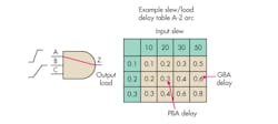
GBA uses the worst-case input slew across all cell inputs to compute the delay through a given cell, resulting in a small amount of pessimism across each multi-input stage. Generally, clock trees are unaffected because they are only single-input cells (inverters or buffers). Therefore, there is only one input slew from which to choose. Figure 1 illustrates the practice of taking the worst slew of a multi-input gate.
PBA, on the other hand, calculates delay beginning at the start point and traces the path all the way to the end point. Only the slews of the input pins along the path are considered. The problem with PBA analysis is that it takes an inordinate amount of time to trace from start point to endpoint and recompute timing based on the actual slew of the pin that is part of the path.
PBA runtimes are more than an order of magnitude larger than GBA runtimes for an equivalent number of paths, severely limiting the use of PBA during timing signoff. It would be impractical to run PBA on all the paths in the design, so users apply PBA to critical or violating paths.
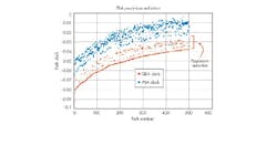
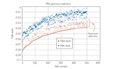
By analyzing the path with reduced pessimism, some timing violations can be waived. Unfortunately, a lot of timing optimization may have already occurred earlier in the closure flow to bring violating paths from negative to positive slack. Utilizing PBA earlier in the flow would have resulted in fewer inserted cells since fewer violations would have been present. Studies at Cadence have shown that PBA analysis on blocks composed of random logic can improve critical net timing by as much as 2% to 3% (Fig. 2).
A marginal reduction in slack pessimism is all that is needed to impact power by reducing the number of inserted cells required to fix timing issues. This also saves cell area and reduces congestion. For processor designs, pessimism reduction leads to higher operating frequencies and performance specifications.
Because of these important benefits, more focus is required from EDA vendors in improving the runtime performance of PBA. If PBA runtimes can be improved by significant amounts, designers can begin to utilize PBA on a larger set of paths and perform their analyses earlier in the design closure flow.
While timing engineers will continue to sign off designs with sweaty palms, EDA vendors must continue to provide viable solutions that model design timing as close as possible to reality. Let’s reduce pessimism due to runtime tradeoffs, improve power and area, and let engineers worry about the real unknowns.
This file type includes high resolution graphics and schematics.
About the Author
Ruben Molina
Product Marketing Director
Ruben Molina is the product marketing director at Cadence. He is responsible for setting product rollout strategy, establishing tool requirements based on customer needs, and assessing the competitive landscape in the areas of pricing, licensing models, and technical capabilities. Previously, he held marketing director positions at Magma Design Automation and Extreme DA, where he was the responsible for directing business development and product marketing for all static timing analysis and parasitic extraction products. In addition, he has held senior management and technical positions at LSI Logic in design methodology, including power, crosstalk, clock distribution, delay prediction, and variation modeling. He also spent several years as an IC designer for Hughes Aircraft, Radar Systems Group. He holds a BS in engineering and an MSEE from California State University, Los Angeles. He is the co-author of seven U.S. patents as well.


