Big changes are ahead for functional verification. The days of being able to rely on register transfer level (RTL) simulation as the primary mechanism for verification are fading and the incumbent electronic design automation (EDA) companies are beginning to respond, though slowly and conservatively. None of them are dealing with the primary need for a verification flow that enables complete horizontal reuse of verification environments from concept to silicon and beyond.
Related Articles
- Interview: Adnan Hamid Addresses Trends In Chip Verification
- Remove The Processor Dilemma From Constrained-Random Verification
- One Verification Model To Drive Them All
Understanding the root cause of the problem with existing verification environments requires a re-examination of the fundamental tenets of verification: two independently derived models of the system are required, and the act of verification is showing that no functionality can occur in the implementation model that is not predicted by the verification model. The act of verification also entails providing models with the necessary stimulus to drive them and collecting results for comparison.
Independently Derived Models
The reasoning for these tenets is sound. If two models are created, each being an independent interpretation of the specification, it is unlikely that a common error will be made in both models. Any differences found during verification are indicative of an error in the implementation, an error in the verification model, or an ambiguity in the specification.
The key problem is that RTL simulation does not have a clean second model with which to perform verification. It relies on a hodgepodge of bits of information contained in the scoreboard, the coverage model, the constraints, the checkers, and, more recently, in assertions, sequences, and virtual sequences. From this collection, verification engineers expected that a simulation-based tool would be able to generate useful tests. As they are now beginning to see, tools cannot work miracles and RTL simulators are too slow to be wasting the amount of time they do executing useless test cases.
Predicted Behaviors
Most test generation environments separate the notion of stimulus generation from results checking. This is a huge problem because it means that stimulus is generated without understanding the ultimate goal of a test or how information will move through a system. It also creates a closure problem because there is no natural coverage model in either the results checking model or the files used to guide the generator. This disconnect between models makes it difficult to ensure that the right kinds of verification are performed at each stage of the design flow and that tests are prioritized in terms of their importance rather than considering all potential bugs to be equal.
Stimulus And Response
When all verification was performed using RTL simulators, the notions of stimulus and response were fairly well defined, or perhaps more properly stated, the verification methodology was driven by the features that RTL simulators presented. For other execution engines, these mechanisms are different.
For example, an emulator can run at speeds orders of magnitude faster than a simulator. If a software testbench is required to create stimulus in a dynamic manner and feed it to the emulator each time step, the emulator will have little effect on overall simulation performance. The stimulus must be aware of the requirements of the execution platform. This becomes even more essential if test cases are to be run on actual silicon, a verification step used by an increasing number of companies these days.
Expanding Role Of Verification
RTL simulation is used for functional verification, defined as ensuring the two independent model descriptions are functionally equivalent for the test cases considered. But in the chips being created these days, especially system-on-chip (SoC) designs, this is not enough. In fact, it’s only the tip of the iceberg.
First, functional verification has become more focused. The incumbent strategy is based on a notion of exhaustive verification, even though it has no notion of what completeness means, nor does it have a concept of priority. Test cases of lesser importance may be executed and used to satisfy a coverage goal, while some of the most essential use cases may go untested. Verification teams want to be able to prioritize the way in which use cases are defined and run. They also want a notion of coverage that does not require a translation of simply stated functional requirements into a set of coverage points that imply an indirect observation that a behavior may have been executed.
As well as the change in priorities, there is an expansion in scope. When RTL verification methodologies were put in place, systems were fairly simplistic in their structure, often composed of a single processor, a bus, a memory subsystem, and a few peripherals. It was easy, using static techniques such as spreadsheets, to estimate the system performance and throughput with a fair degree of precision. That is not the case now, and those static methods are inadequate for SoC verification. Instead, complex tests have to be created to stress aspects of the system and determine whether the performance goals are being met. This has become a necessity for the verification environment.
As another aspect of growing system complexity, it made sense in those earlier chip designs to remove the processor when performing verification. In an SoC, the processors are the main drivers of behavior and must be included in the verification environment. This requires extending the notion of stimulus generation to the generation of code to run the embedded processors.
Today’s SoCs are constructed from several complex subsystems, each of which includes a processor. This hierarchic composition of systems creates demands on the verification environment in terms of composition and reusability. Consider the design flow. Many companies now start with an electronic system-level (ESL) virtual prototype of the complete system. This is used to make architectural tradeoffs, verify the throughput and communications aspects of the chip, and, in some cases, make intellectual property (IP) selection. The architects need to be able to execute complete end-to-end scenarios on the system model.
Then, the system is hierarchically decomposed into smaller blocks and implementation starts on each block. Those individual blocks are verified and integrated into larger blocks, which need to be verified. This continues until the entire SoC has been reconstructed and system-level tests can be executed again. As the integration process is happening, the verification environment may need to migrate to an emulator to be able to execute longer and more useful tests. The complete system may be placed on an FPGA prototype. A single verification environment means that the verification models must be composable and that the associated verification tools must comprehend the full range of verification platforms.
Horizontal Reuse
It is now possible to think about what horizontal reuse means in the context of functional verification. The verification flow, from product inception through actual silicon, must be driven from a single description that should be a combination of the separated piece-meal models used today, including scoreboard, coverage model, constraints, checkers, assertions, and sequences. This model must be hierarchical and operate in a hierarchical environment without needing to modify each piece when composed into larger models. The flow is driven from a tool suite that can utilize the unified model and generate suitable test cases tuned to the stage of the verification flow, execution engine, and objectives of the test, whether functional, performance-related, or power-related.
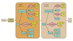
Graph-based scenario models are one way in which the requirements for this type of flow can be captured. Graphs work because they define the capabilities of the system as dataflow capabilities that they provide and restrictions on that dataflow. It naturally follows that as these graphs are composed into larger graphs, all of the capabilities at the lower level remain valid at the higher level, unless the integration rules out certain paths of the sub-graph (Fig. 1).
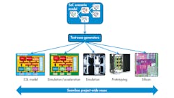
Tools are available to generate test cases targeted at virtual prototypes, RTL simulation, simulation acceleration, emulation, FPGA prototypes, and even real silicon in the lab. A common graph-based scenario model drives these test cases. They can be optimized for each platform, for example, generating much longer tests for hardware platforms than for simulation. Test cases can verify the SoC’s functionality, performance, and low-power operation. The verification team can provide guidance to the generation process simply by adding constraints and biasing to the graph (Fig. 2).
A final advantage of the graph-based methodology is the ability to refine the graph over time. At the beginning of the design flow a minimal graph, showing only the primary use cases, can be described and used for functional verification on the very earliest virtual prototypes. As the design is refined and additional features added, the graph can be expanded. The incremental nature of this approach, combined with horizontal reuse across platforms, enables the SoC design and verification flows to be kept in lockstep throughout the project. This results in a shorter and more predictable schedule and higher design quality than the “design first, verify later” methodology used widely today.
Adnan Hamid is cofounder and CEO of Breker Verification Systems. Prior to starting Breker in 2003, he worked at AMD as department manager of the System Logic Division. Previously, he served as a member of the consulting staff at AMD and Cadence Design Systems. He graduated from Princeton University with bachelor of science degrees in electrical engineering and computer science and holds an MBA from the McCombs School of Business at the University of Texas.
About the Author
Adnan Hamid
CEO
Adnan Hamid is the founder and chief executive officer of Breker Verification Systems, and inventor of its core technology. He has more than 20 years of experience in functional verification automation and is a pioneer in bringing to market the first commercially available solution for Portable Stimulus. Prior to Breker, Hamid managed AMD’s System Logic Division and led its verification group to create the first test case generator providing 100% coverage for an x86-class microprocessor. Hamid holds 12 patents in test case generation and synthesis. He received Bachelor of Science degrees in Electrical Engineering and Computer Science from Princeton University, and an MBA from the University of Texas at Austin.


