Smart-Building Megatrends: How to Handle the Power
Download this article in PDF format.
Buildings—with a carbon footprint even greater than that of the transportation sector—account for a significant portion of the total energy consumption in the United States. The American Architecture 20301 standard recently issued a challenge for all existing buildings to cut energy use by 50% compared with 2005 levels, and for all new buildings to be completely carbon neutral by 2030. In other words, they should supply most of their energy needs using renewable sources.
Many large- and medium-sized cities already require commercial building owners to disclose actual green building performance2 to tenants, buyers, and, in some cases, the public. By utilizing modern control and automation techniques, smart buildings can have significant energy savings, protect the environment, improve the health and safety of their occupants, and enhance quality of life.
Building automation design (Fig. 1) introduces issues of energy efficiency, solution size, system safety, and reliability of the electronics used. This article discusses the megatrends underlying the smart-building revolution and their associated system challenges, from networking protocols all the way down to the hardware. It then examines new solutions for power management through several case studies.
1. In building automation design, a variety of issues emerge such as energy efficiency and system safety.
Megatrends in Building Automation
Building operators increasingly manage larger buildings remotely, via the cloud. Their software platforms provide performance monitoring, data analytics, visualization, fault detection and diagnostics, and portfolio energy management. These automation systems can monitor several variables in real time and analyze historical data to adjust the devices to provide comfort to users while complying with government regulations and tariff policies.
By networking the equipment data to the cloud, analytics can be run in real time using advances in artificial intelligence (AI) to determine the action to be taken. The most prevalent use of automation in buildings is in HVAC (heating/ventilation/air conditioning), lighting, monitoring, access control, fire detection, and closed-circuit television (CCTV) surveillance systems.
A building’s energy is measured by energy use intensity (EUI) and is noted in kilo British thermal units per square foot (KBTU/SF). One KBTU equals 3.142 kWh.
The Building Automation System
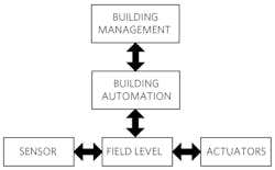
Building automation system architecture (Fig. 2) includes different layers for management, control, and the field.
2. Smart building systems involve different layers: management, control, and the field.
The management layer operates and controls the smart building from one central location, recording and optimizing data as necessary. Problems are spotted in real time and action can be taken immediately. This layer uses network protocols like BACnet and Modbus.
The control layer (the building automation block shown in Fig. 2) deals specifically with the building’s equipment control at the hardware level. Here, decentralized protocols like KNX and LonWorks are used.
At the field layer, intelligent sensors and actuators collect data and perform tasks. For example, the lighting level is sensed and automatically adjusted to match the time of day. Shading is provided to ensure optimal use of natural light without glare.
The Technology Enablers
All of this intelligence, networking, and control is enabled by phenomenal advances in hardware and software. At the field level, it’s manifested through controllers, sensors, I/Os, and actuators. A controller can be a programmable logic controller (PLC), motor/motion controller, or a distributed control system (DCS) using advanced processors and microcontrollers. Sensors can be either digital or analog and used to measure temperature, humidity, ventilation, and occupancy. Actuators can be used in locks, window alarms, security camera positioning, solar panels, blinds, and other moving mechanisms.
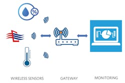
In a modern building, sensors and actuators can communicate on wired or wireless gateways to the control center. They’re powered by batteries or wired dc voltages, typically in the 5- to 24-V+ range. In Figure 3, the wireless sensors connect to the monitoring system via a gateway to detect the humidity, HVAC, and temperature.
3. Wireless sensors at work.
The controller receives inputs from sensors on the field, processes them, and drives the proper actuators. Today’s sensors and actuators are equipped with internal processors that make simple decisions locally without the need to escalate to the controller, thereby improving throughput.
The Challenges
The proliferation of intelligent, internet-connected equipment in the smart building requires a proliferation of processors and connectivity interfaces into every controller, sensor, and actuator in the field. This, in turn, places new requirements on system hardware: reduced component size to fit additional electronics in the same chassis, improved energy efficiency to perform within the same or lower thermal budget, and increased electrical/mechanical safety and reliability to reduce downtime. In summary, the challenges for the electronic components are:
1. Higher energy efficiency
2. Reduced solution size
3. Increased safety and reliability
In the following sections, we will present a few examples of how power-management electronics can come to the rescue in each case.
The Solutions
High Energy Efficiency
The smaller PCB size that results from miniaturization presents a challenge for thermal dissipation. Thermal-management options, such as heatsinks, are ruled out since board space is at a premium. Fans for forced airflow can’t be used due to sealed enclosures that prevent ingress of dust and pollutants. Therefore, it’s crucial that the power-supply solution is extremely efficient, while delivering higher power and occupying a smaller area than ever before.
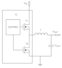
Often sensor and actuator applications are characterized by a 24-V nominal dc voltage bus that has its history in old analog relays and remains the de facto industry standard. However, the maximum operating voltage for industrial applications is expected to be 36 to 40 V for non-critical equipment, while critical equipment, such as controllers, actuators, and safety modules, must support 60 V (IEC 60664-1 insulation and 61508 SIL standards). Popular output voltages are 3.3 and 5 V, with currents varying from 10 mA in small sensors to tens of amps in motion control, CNC, and PLC applications. Thus, the obvious choice for building and industrial control applications is a step-down (buck) voltage regulator (Fig. 4).
4. Fully integrated synchronous buck converter.
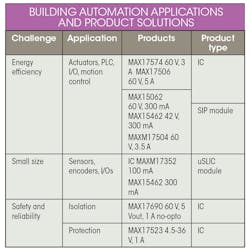
Buck converters that achieve high efficiency for high-performance systems are reported as an example in the Table under “Energy Efficiency.”
Summary of building automation applications and example product solutions.
A Word of Caution on Maximum Input Voltage
While 24 V is the nominal rail for many applications, carefully consider the maximum operating voltage. Select from 28-, 36-, 42-, or 60-V input power-management solutions that are available on the market today. With a margin of only 4 V, clearly 28 V is too close to 24 V to provide a reliable margin. Many standards require 60-V tolerance, removing the need to make a choice.
It’s tempting for many designers to choose a device with a 36-V maximum input. However, using a 36-V input is a high-risk approach for sensors and encoders that work on a 24-V rail. Even if transient-voltage-suppressor (TVS) diodes are used for surge protection, they have a wide tolerance and could still expose equipment to excessive voltages. Unless you’re certain and have modeled every possible surge scenario resulting from long cables and PCB traces, use devices with a 42- or 60-V maximum operating voltage even if the standard doesn’t require it.
Reduced Solution Size
Sensors have become ubiquitous in the smart-home environment. In turn, sensor electronics are becoming more complex, requiring on-board voltage regulators to deliver power more efficiently with minimal heat generation. How do you safely deliver low-voltage power to tiny sensors, while minimizing solution size and maximizing efficiency? In this section, we will review a typical sensor architecture and provide a simple solution to this challenge.
Smart-Home Sensor Applications
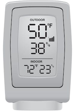
Sensors (Fig. 5) detect and diagnose many parameters and make decisions. They must be durable and reliable regardless of the environment.
5. Temperature and humidity sensor.
Sensors may be located anywhere in the building. The sensor “box” is powered by a voltage regulator, which delivers the appropriate voltage to the ASIC/microcontroller/FPGA, AFE, and the sensing element.
Safe Low-Voltage Operation
The sensor is typically powered by a 24-V dc power source. However, a building can be a very challenging environment to install sensors, which require long cable connections to the power source that result in high-voltage transients. Accordingly, the step-down converter inside the sensor must withstand voltage transients of 42 or 60 V, which are much higher than the sensor operating voltage. As discussed before, for 24-V rails, it’s best to rely on devices that have an operating maximum of 42 V.
Examples of power solutions that meet the requirements of building automation sensors are given in the Table under “Small Size.”
Increased Safety and Reliability: Isolation
Isolated dc-dc voltage regulators are found in the most diverse applications. Although an isolated solution is more complex than a non-isolated one, there’s still an expectation for it to fit in a small space and be highly efficient. In this case study, we discuss the reasons for isolation in low-voltage power-conversion systems.
Low-Voltage Isolated Systems
According to SELV/FELV regulations, input voltages below 60 V are considered inherently safe to touch, but the need for isolation in this operating range is still pervasive for functional safety and reliability reasons. In this voltage range, the power-supply electronic load, typically a very delicate and expensive microcontroller, needs protection. It could readily self-destruct if accidentally exposed to high voltage.
Isolation also prevents ground loops, which occur when two or more circuits share a common return path. Ground loops produce parasitic currents that can disrupt the output-voltage regulation as well as introduce galvanic corrosion of the conducting traces. This is a phenomenon that degrades equipment reliability.
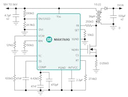
As an example, a peak current-mode, fixed-frequency switching controller is reported in the Table under “Safety and Reliability” (Fig. 6). It’s specifically designed for the isolated flyback topology operating in discontinuous conduction mode (DCM).
6. No-opto flyback controller.
Increased Safety and Reliability: Protection
Protection circuits are the unsung heroes of today’s electronics. The long electrical chain, from the ac line to the digital load, no matter the application, is interspersed with fuses and transient voltage suppressors of all sizes and shapes. While common issues like ESD protection and pin-to-pin short circuits are handled within ICs, there are additional aspects to consider for safety and reliability.
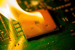
Along the electrical path, electrical stressors—such as inrush currents due to storage capacitors, reverse currents due to power outages, overvoltages, and undervoltages induced by inductive load switching or lightning—can damage precious electronic loads. This is true for microprocessors and memories, which are built with fragile submicron, low-voltage technologies. Layers of protection are necessary to handle these potentially catastrophic events (Fig. 7).
7. Unprotected CPU on fire.
Protection electronics must handle fault conditions such as overvoltage/undervoltage, overcurrent, and reverse-current flow within the limits of its voltage and current rating. If the expected voltage surge exceeds the protection electronics ratings, additional layers of protection are added in the form of filters and TVS devices.
Integrated Solution
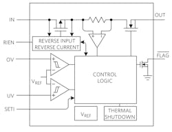
Figure 8 shows an integrated protection circuit that addresses overvoltage, reverse polarity, current limiting, reverse current, and short-circuit protection with all of the benefits of an e-fuse and surge stopper. Designers can easily implement robust protection in their smart-building equipment and pass compliance with configurable pins to set UVLO/OVLO, current limit, real-time voltage, current monitoring, current thermal foldback, thermal shutdown, and other features.
8. Integrated protection in a single IC.
An example of a highly integrated protection IC is reported in the Table under “Safety and Reliability.”
Summary
As the current trend of automation and data exchange in the smart building continues unabated, it will rely on new technologies and approaches to achieve higher comfort, reduce carbon footprint, and improve cost. The adoption of these technologies introduces challenges in terms of energy efficiency, miniaturization, and system reliability. For each challenge discussed, a few power-management ICs were presented to help designers realize great building automation systems. These power-management solutions overcome the critical challenges faced by today’s smart buildings.
Anthony T. Huynh is Principal Member of the Technical Staff, Industrial Power, and Nazzareno Rossetti, PhD is an EE at Maxim Integrated.
References
About the Author
Anthony T. Huynh
Principal Member of the Technical Staff, Industrial Power
Anthony T. Huynh (a.k.a. Thong Anthony Huynh) is a Principal Member of Technical Staff (MTS), Applications Engineering, at Maxim Integrated. He has more than 20 years of experience designing/defining isolated/non-isolated switching power supplies and power-management products.
Nazzareno Rossetti
PhD EE
Nazzareno (Reno) Rossetti, a PhD EE at Maxim Integrated, is a seasoned analog and power-management professional, a published author, and holds several patents in this field. He holds a doctorate in Electrical Engineering from Politecnico di Torino, Italy.


