Board-Level Qualification Testing for Rad-Hard MOSFET Packaging
For Defense Logistics Agency (DLA) QPL qualification, high-reliability rad hard MOSFETs undergo extensive screening and quality-conformance testing to ensure that devices perform to specification in the harshest environments, sometimes for 15 years and longer. Both the US and European communities have developed specifications detailing quality conformance testing sequence.
In the US, DLA’s MIL-PRF-19500 and MIL-STD-750 govern the quality conformance testing sequence performed on discrete MOSFET semiconductors manufactured to JANS or JANTXV levels. In Europe, ESA’s ESCC 5000 is the standard for discrete semiconductors, hermetically sealed and die.
These tests are performed at the chip or package level, per applicable standards. In real life, rad-hard MOSFETs are mounted to boards for use in subsystems, such as DC-DC converters, intermediate bus converters, motor controllers, and others. Yet PCB level performance testing is not required by DLA or MIL standard. That’s why with our newest package designs, International Rectifier HiRel (IR HiRel) developed a series of board-level qualification tests to provide even greater levels of assurance to our customers.
Packaging for higher reliability
In space-rated power electronics, reliable attachment of surface-mount hermetically-packaged MOSFETs to PCBs has dogged space system designers for years. Material differences, specifically coefficient of thermal expansion (CTE) mismatch of the board and surface mount power package, can make it difficult to maintain reliable solder joints between the PCB and SMD package. CTE mismatch also makes it challenging to preserve the sealed integrity of a hermetically packaged silicon power MOSFET.
IR HiRel developed the SupIR-SMD package as a way to overcome the issue of CTE mismatch between a power semiconductor and PCB. Designed for direct-to-PCB surface mount attach, SupIR-SMD enables the shortest thermal conduction path to help optimize power system efficiency. Standard qualification for new devices housed in SupIR-SMD is JANS level per MIL-PRF-19500.
Typical applications range from space exploration vehicles to communications, navigation, and observation satellites, and more. These vehicles may fly at low Earth, geostationary, or highly elliptical orbits, or interplanetary, deep space missions. While the flight environments may differ greatly, we know that each space program must be evaluated vis-à-vis its mission profile needs including, but not limited to:
-Reliability
-Radiation tolerance
-Environmental stresses
-Expected mission life cycle
Beyond that, space electronics must withstand tremendous forces from the launch environment itself. Extreme shock and vibration, ESD discharge, vast temperature swings and more…high-reliability electronics are designed to endure much harsher conditions than COTS parts were ever meant to face. IR HiRel’s rad-hard silicon power MOSFETs undergo extensive testing at the chip or package level per the applicable standard(s) to ensure performance to specification in the harsh space environment. In this case, it is typically qualified to MIL-PRF-19500 JANS level.
The goal of PCB-level test procedures is to validate the package design integrity through next-level assembly and environmental testing operations. Broadly speaking, these board-level protocols include:
-Random vibration
-Mechanical shock
-Temperature cycling
-Post-test inspection for fine and gross leak, and cross-sectioning of solder joints
Sequential Qualification Tests
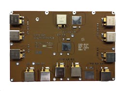
For example, to qualify the SupIR-SMD package at the board-level, we mounted several packages in various orientations and positions on a representative PCB. With polyimide glass fiber as the board material, per IPC 4101/411, the PCB had eight layers and an overall board thickness of 1.8 mm. Using SN63Pb37 solder and RMA flux, we attached components to the PCB. The solder stencil was 8 mils thick, with a 90% ratio of opening to pad size. Prior to testing, we inspected the whole assembly according to IPC-J Standard, Space Addendum2. Then we subjected the board to random vibration, mechanical shock and temperature cycling. In order to proceed through each stage of mechanical stress tests, the assemblies had to remain failure-free.
Random vibration
The random vibration test simulates spacecraft launch and Grms (root-mean-square acceleration) that the electronics must endure. We tested in accordance with ECSS-Q-ST-70-38C3, with the test level increased to 40 Grms. Note that this standard includes by reference test conditions outlined in ECSS-Q-ST-70-08C4. Based on IR HiRel’s space power electronics experience and our customer needs, increasing the test conditions more accurately reflects what parts actually face in launch settings. This is also closer to MIL-STD-883J5 Test Method 2026, Condition 1J, which requires 36.6 Grms.
Our test setup vibrated the SupIR-SMD board assemblies in three dimensions, up to 40 Grms for five minutes in each dimension, which exceeds the ECSS standard. For comparison, IPC-TM-6505 test condition F is the closest equivalent to these ECSS and MIL-STD-883 standards, but far less intense, with a required test level of only 10.9 Grms.
Mechanical shock
The mechanical shock test simulates the sudden and extreme accelerations or decelerations caused by launch sequence engine separations. As a baseline reference, we started with MIL-STD-883J4 Test Method 2002.5, Condition B, which is part of IR HiRel’s usual package-level qualification for MOSFETs. We also considered ECSS-Q-ST-70-38C5, which specifies that shock levels should “meet intended mission with margin.” IPC-TM-6506 Test Method 3.8 A, Condition E is similar to the MIL standard, but less intense, specifying a peak acceleration of 1,000 Gs with three shocks in each direction per axis and a pulse duration of 0.5 milliseconds.
For our PCB-level tests, we subjected the SupIR-SMD assemblies to a minimum of 1,500 Gs peak acceleration for 0.3 milliseconds, shocking them in positive and negative directions each in X1, Y1 and Z1 directions. With six shocks per axis, we performed 18 shocks in total. These test parameters are in line with our global customer requirements for standard space equipment.
Temperature cycling
This test simulates the extreme operational temperatures space electronics must withstand in flight. We subjected the SupIR-SMD assemblies to the thermal cycling based on ECSS-Q-ST-70-38C (-55°C to 100°C). Specifically for the board assemblies, we applied 500 temperature cycles from -55°C to 100°C with a maximum 10°C/minute ramp and a minimum 15 minute dwell time at each extreme, which is more intensive than specified by the standards for package qualification.
These parameters are similar to IPC-9701A7, but with an increased dwell time and decreased ramp rate. MIL-STD-750F for package qualification isn’t directly comparable to either the ECSS or IPC standards which both use a test condition from -55°C to 100°C, whereas MIL-STD-750F specifies -55°C to 85°C. ECSS-Q-ST-70-38C and MIL-STD-750F standards also specify fewer number of cycles, 200 and 20, or as specified, respectively.
Cross-section inspection of solder joints
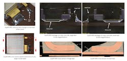
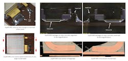
After completion of these tests, we cross-sectioned the assembly solder joints in accordance with ECSS-Q-ST-70-38C, which specifies requirements for qualification of PCB technology. Pass criterion for this test is that cracks in the solder shall not exceed 25% of the lap connection in the critical zone. There shall also be no cracks in the ceramic. Since the ECSS standard doesn’t allow for any ceramic cracks in SMD devices, it is stricter than the MIL-STD-7508 Test Method 2071 and MIL-STD-883 Test Method 2009 alternatives.
Conclusion
Satellite manufacturers worldwide use hi-rel DC-DC converters, and board-level tests subject the power semiconductors to the same rigors expected during space flight lifetime. While there are no mandated industry standards for this type of testing, best-practice board-level protocols should either comply with or exceed the test conditions selected as baselines. We strongly believe this proactive approach and added level of qualification gives a high degree of assurance. Silicon-based technologies remain a trusted choice for use in high-reliability space applications. With its proven heritage, performance, robustness, and well-known screening and reliability standards, pushing to greater levels of test acceptance helps extend that confidence to next-generation silicon platforms.
References:
1 IPC-4101C, Specification for base materials for rigid and multilayer printed boards, http://pmo4ab2ac.pic34.websiteonline.cn/upload/IPC-4101C2009-08.pdf
2 Joint Industry Standard, Space Applications Electronic Hardware Addendum to J-STD-0001D Requirements for Soldered Electrical and Electronic Assemblies https://www.ipc.org/4.0_Knowledge/4.1_Standards/J-STD-001DS-addendum.pdf
3 ECSS-Q-ST-70-38C Rev. 1 Corrigendum 1, High-reliability soldering for surface-mount and mixed technology https://ecss.nl/standard/ecss-q-st-70-38c-rev-1-corrigendum1-high-reliability-soldering-for-surface-mount-and-mixed-technology-12-september-2018/
4 ECSS-Q-ST-70-08C, Manual soldering of high-reliability electrical connections https://ecss.nl/standard/ecss-q-st-70-08c-manual-soldering-of-high-reliability-electrical-connections/
5 MIL-STD-883J, Test procedures for complex monolithic microcircuits http://everyspec.com/MIL-STD/MIL-STD-0800-0899/download.php?spec=MIL-STD-883J__METHOD_5010-TO-5013.047062.pdf
6 IPC-TM-650 https://www.ipc.org/test-methods.aspx
7 IPC-9701A, Performance test methods and qualification requirements for surface mount solder attachments, https://shop.ipc.org/IPC-9701A-English-D
8 MIL-STD-750, Test methods for semiconductors, http://everyspec.com/MIL-STD/MIL-STD-0700-0799/MIL-STD-750F_39654/


