Understanding and Measuring Power-Supply Transient Recovery Time
This file type includes high-resolution graphics and schematics when applicable.
Power-supply transient recovery time is the specification of a dc power supply. It describes how quickly the power supply will recover from a transient load condition on the output of the power supply.
With an ideal power supply operating in constant voltage, the output voltage would remain at the programmed value regardless of the current being drawn out of the power supply by the load. A real power supply, however, cannot maintain its programmed voltage when there’s a rapid rise in load current.
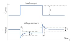
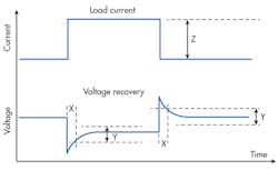
In response to a rapid rise in current, the power-supply voltage will droop until the power-supply regulation feedback loop brings the voltage back up to the programmed value. The time it takes for the value to get back to the programmed value is the load transient recovery time (Fig. 1).
Note that if the load-current transient is not a fast transient, but rather slowly rises or falls, the power-supply regulation feedback loop will be fast enough to regulate and maintain the output voltage without any visible transient. As the current transient’s edge speed increases, it exceeds the power-supply feedback loop’s ability to “keep up” and hold the voltage constant, resulting in a load transient event.
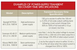
The power-supply transient recovery time is measured from the beginning of the load-current transient to when the power supply settles down and again reaches the programmed value. But anytime you specify “reaches a programmed value,” you must specify to within a tolerance band. Thus, power-supply load-transient recovery time is specified as the time required to reach a tolerance band of some percent of the programmed value, some percent of the rated output, or even a fixed voltage tolerance band. The table shows some examples of power-supply transient specifications.
Looking at the Keysight N7952A power supply, you can see that the transient recovery-time tolerance band is specified as 100 mV. When measuring transient recovery time, if the output voltage is 25 V, you must measure how long it takes the power supply to recover back to within ±100 mV around 25 V.
Power Amplifiers Exemplify Why Transient Recovery Time is Important
Let’s look at an example application where dc power-supply transient response is important. When testing power amplifiers (PA) used in mobile devices (such as cell phones or tablets), it’s very important for the dc bias voltage into the device under test (DUT) to remain at a fixed and stable voltage. If the voltage were to fluctuate or change during the test, the proper test conditions are not maintained and the resulting RF power measurements on the DUT will not be correct.
In this case of the PA, the situation is exacerbated due to the current profile. The PA transmits in pulses, and therefore pulls current from the dc bias in pulses. These pulses have fast edge rates and therefore present significant load transients on the dc bias. Each time the PA pulses on, it draws high current, which drags down the dc bias power supply. The power supply will recover quickly; however, during the time when the power supply is responding to the transient, its voltage is not at the desired value for the test. Once the power supply recovers, the PA will then operate under the right test conditions and thus it becomes possible to make the proper RF power measurements.
With billions of PAs being manufactured and tested each year, test throughput is critical. If the power supply recovers slowly, it adds test time to the PA and therefore slows down manufacturing test throughput. PA manufacturers, therefore, look for fast recovery power supplies to ensure they can achieve maximum manufacturing test throughput. They look to the transient recovery time specification to determine which supply will be best for their application. So, the power-supply vendor needs to be able to accurately measure power-supply transient recovery time in order to present the best possible specification to PA manufacturers.
Measuring Transient Recovery Time
The challenging part of measuring load-transient recovery time is determining when the voltage enters the tolerance band. The average voltmeter can easily measure if the dc output voltage is within the tolerance band. It’s a slow instrument, though, and will not be able to sample fast enough to give a meaningful time measurement with adequate resolution to say how quickly the voltage entered the tolerance band.
Looking beyond the average voltmeter, certain high-speed voltmeters can measure tens of thousands of readings per second with enough accuracy to detect when the power-supply voltage precisely enters the tolerance band. One such example is Keysight’s 34470A DMM. As transient recovery times improve, these voltmeters, even capturing data at 50 ksamples/s, become too slow to capture the fast recovery time.
A scope would be a more reasonable tool to use, as it can easily capture and visualize very fast transients. The average scope, though, typically has 1%-3% vertical accuracy and 8-bit resolution. Consequently, it struggles to provide enough vertical accuracy and resolution to precisely locate when the dc output voltage reaches the narrow tolerance band.
By putting the scope in ac coupling, you try to zoom in on the tolerance band. However, error will be introduced as the post-transient settled dc level will be distorted due to the ac coupling. This could make it difficult to precisely identify the post-transient dc level within the tolerance band as the settled dc voltage is being “pulled down” by the ac coupling.
Another option would be to leave the scope in dc coupling, but use a large dc offset on the scope in order to zoom in on the tolerance band. This works well with dc outputs in the 0- to 10-V level, but as the dc output climbs, the dc offset must also climb. With big dc offsets, the minimum volts/division must also increase to support the big dc offset, resulting in less measurement resolution on the tolerance band.
For power supplies with a wider voltage tolerance band, scopes can be used to make these measurements. In fact, Keysight oscilloscopes offer built-in power-analysis software that make transient response measurements via turnkey operations (check out www.keysight.com/find/scopes-power). The highest-performance scopes, with 10 or 12 bits of resolution, have more flexibility and more advanced front ends, allowing them to make these measurements even for narrow voltage tolerance bands. However, these scopes are not as common on the average lab bench.
For power supplies with narrow voltage tolerance bands, a high-performance power quality analyzer can make this measurement—provided it has single-shot measurement capability. Single-shot measurement is needed because the transient is a single-shot event triggered by the rising edge of the current pulse. Alternatively, if you can generate a repetitive load-current transient, such as a square wave where the current jumps between high and low current values, you can use a power analyzer without single-shot measurement to capture the repeated transient event.
High-performance power analyzers have better than 0.1% vertical accuracy, 16-bit resolution, and digitization speeds of 1 Msample/s or more. This combination of fast digitization and accurate voltage measurement allows you to easily measure power-supply load transient response and identify when the narrow tolerance band is reached. Since a power analyzer can directly measure voltage and current without probes, you can quickly set up this measurement to trigger from the rising edge of the current and then measure the voltage recovery time.
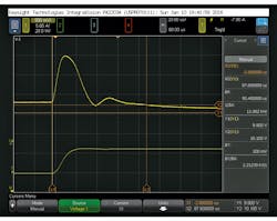
One power analyzer with this capability is the IntegraVision Power Analyzer (Fig. 2), which provides single shot 5-Msample/s digitizing at 16 bits simultaneously on both voltage and current, with 0.05% basic accuracy, all displayed on a large color touchscreen. The measurement is being made on a 10-V supply being pulsed between 2A and 8A. Its transient recovery band is ±100 mV.
Using the IntegraVision’s two Y markers, you can identify the top (10.1 V) and bottom (9.9 V) of the voltage tolerance band. Then, with the two X markers, you can identify when the transient begins on the current waveform with marker X1 and when the voltage enters the tolerance band with marker X2. The time difference between X1 and X2 is the transient recovery time, measured as 90.4 μs.
About the Author
Bob Zollo
Solution Architect for Battery Testing, Electronic Industrial Solutions Group
Bob Zollo is solution architect for battery testing for energy and automotive solutions in the Electronic Industrial Solutions Group of Keysight Technologies. Bob has been with Keysight since 1984 and holds a degree in electrical engineering from Stevens Institute of Technology, Hoboken, N.J. He can be contacted at [email protected].


