Download this article in PDF format.
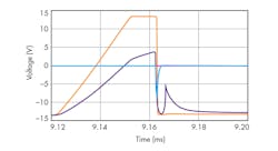
My article about voltage-to-frequency converters had a figure that showed the waveform on the base of a unijunction transistor (Fig. 1). This was a PSpice waveform generated by OrCAD 9. After the UJT base reaches 4 V, the base impedance collapses and the base voltage drops precipitously. The surrounding circuitry draws the base down to −13 V. That’s all good and well, but there’s a funny spike in the waveform after the voltage collapse. About 6 µs after the voltage collapse, the waveform rises back up to −5 V. The waveform then does a nice exponential decrease back down to −13 V.
1. This Spice simulation has a blue trace that shows the base of a unijunction transistor operating as an oscillator. The waveform peaks after it rapidly falls, but that doesn’t matter in the operation of the circuit. Not only that, the peak might just be a Spice artifact.
At the time I wondered if this was a case of Spice lying, the way Bob Pease said it does. I can see a complex circuit with bad models giving bad output. When Spice was invented at UC Berkeley in 1968, one of the things they worked very hard on was making models for transistors and diodes. Later work improved those models with behavior over temperature. With the 2N2646 UJT being a rather obscure and obsolete part, it was hard to say if there were any good models available for the transistor.
Perhaps I will find some of that part on eBay and build up this circuit. I suspect the waveform will have the same little peak in it like that in the Spice simulation. That peak might bother you the way it bothered me. Engineers hate a mystery; we are a fundamentally curious breed. What is important to remember is that that little peak does not matter to the performance of the circuit. No matter how much it bothers you, as long as it does not damage anything or cause electromagnetic interference (EMI), it’s a perfectly good circuit you can send to production.
Reality Check
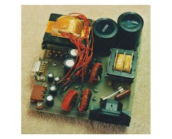
2. This flyback power supply uses a simple control chip. If you don’t know how to measure the high-voltage switch node, the waveform can look suspicious.
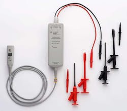
Even worse time-wasters can be funny-looking waveforms that are not even real. I had this happen with my flyback power supply design (Fig 2). Young and dumb, I did not have an isolated transformer so that I could use single-ended scope probes. I also did not have a high-dollar differential-input-powered scope probe (Fig. 3). I had a very nice Hitachi 100-MHz oscilloscope that had served me very well for years. So I did that old trick where you invert one of the channels, and then clip the grounds together between the normal channel and the inverted one, and voilà, a poor-man’s differential probe setup.
3. This high-voltage differential oscilloscope probe from Keysight costs around $1700, but can measure signals up to 1400 V between its differential inputs. Not only that, it can do this with a 1000 V of common-mode voltage on the inputs. This is the right probe to examine switching power supplies.
I was probing the switch node, and when the flyback transformer discharged, there was a funny bump or hiccup in the falling waveform. I chased it for a day. Since this was a low-impedance power circuit node, there had to be energy going somewhere to put in that bump. There was no bump in the waveform. As Texas Instruments amplifier application engineer Paul Grohe explained to me years later, you can’t just “invert” an analog scope channel and expect it to behave like the non-inverted channel. To see Paul in action, here he discusses how to build a microgram scale:
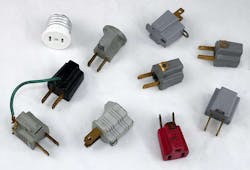
I realized it was the scope putting in the bump when I used one of those three-prong to two-prong outlet converters (Fig. 4). It disconnects the ground if you don’t hook up the little wire or screw in the tab. Then when you hook the “ground” lead of your scope probe to the negative side of a full-wave bridge, it will not blow up the ground wire. It will electrify the entire oscilloscope chassis. If you touch anything metal, including the delay time position knob, you will be electrocuted. You also have to put the scope in a piece of cardboard and make sure it’s not touching any other items. This is dangerous and I would recommend you get an isolation transformer instead.
If you over-voltage an oscilloscope channel, the waveform will be meaningless as it recovers. That recovery might take nanoseconds or it might take many microseconds. That’s why measuring amplifier settling time is so tricky. You have a large step in the signal, and you are trying to measure the much smaller ringing in the waveform after the step. That’s why Jim Williams did an entire app note on settling time back in 1985. As amplifiers get faster, measuring settling time is even more challenging.
Grohe and I were attending a seminar where a well-known speaker was showing settling-time waveforms, and he just let the scope take the overload. A digital scope has analog amplifiers in the acquisition deck. They act funky when you hit them with an over-voltage just like amplifiers in an analog scope. The speaker admitted they did understand some little bumps in the waveform. Grohe and I knew better. The entire waveform was suspect, since the amplifiers in the ‘scope were recovering from overload.
4. These three-prong to two-prong converters can be really dangerous if you use them to isolate your oscilloscope. You can take single-ended measurements on power supplies, but the entire ‘scope chassis will have hundreds of volts on it. That includes the metal knobs on the front panel.
A different situation where the waveform didn’t matter was in a laser-driver chip I worked on for DVD recorders. My company had just developed a fast, high-performance bipolar process. We used it in the laser-driver chip. Since it was bipolar and not CMOS, the “corners” of the pulses were much sharper. We just figured that had to be good; it looked a lot better on an oscilloscope. The problem was that fancy bipolar process was more expensive than a CMOS process. A competitor used CMOS, and with better pricing, was able to win the socket. A pretty waveform does not mean a better part if a cheaper part with a worse waveform still gets the job done.
The Ugly Side of Pretty Simulations
One problem with computers is that they make such pretty pictures and fancy graphs we tend to believe them, even when they don't matter. I interviewed a guy at a strain-gauge company. He said he would instrument a casting and then test its strength. The part would break at a much lower load than the design engineer intended. The design engineer stormed into the lab, claiming the test engineer did something wrong. He showed pretty colored finite-element-analysis computer simulations. They were so pretty. They were so colorful. Only thing is, they were so wrong. It turns out when a casting cools off in the mold, large internal stresses often get generated by the solidification of the metal. The design engineer did not account for these stresses in his fancy computer simulation.
The fact that simulations start with so many assumptions is why Bob Pease was so dismissive of them. Sure, if you are an IC designer with an entire department that makes sure the Spice results match the behavior of the transistors, you can get trustworthy Spice results. Yet every analog designer I know has been burned by a process that did not behave like the model when a bunch of different devices are next to one another on a die. For system engineers, the quality of models can make simulations meaningless.
I agree that if your circuit does not work in simulation, it won’t work in real life. The thing that trips up so many engineers is that a circuit that works just dandy in Spice will often fail miserably when built in the lab, or worse yet, put into production.
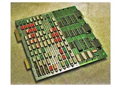
5. This wire-wrap board was a prototype controller for a semiconductor spin-coating machine. It used a dual-port memory to connect its local microprocessor to the host.
One final anecdote of when a waveform does not matter. I once designed a dual-port memory for a spin-coater control board (Fig. 5). A spin-coater is a semiconductor machine that spins the photoresist onto the wafer so that it can be later exposed in a lithography step-and-repeat machine. The new control board had to have a microprocessor, but the original one was just a dumb peripheral card.
Consequently, I had to get things done in the read or write cycle of the host microprocessor. This was the old days, so there were many microseconds to do this. Yet there was not enough time to latch the states of the dual-port memory. Latching outputs eliminates any glitches as the logic settles down. My circuit did generate glitches, but those glitches occurred when the host micro had the bus in a tri-state mode that was not affected by the glitch. It worked fine.
I took the schematic of the dual-port memory to an interview for an optical disk storage startup. I told the hiring manager that I just did this design, and that it did not use latches to make it much faster. He started a vehement argument with me. He insisted you had to latch the outputs of the circuit or it would glitch. I told him that was true, and my circuit did glitch, but it did not matter since the glitches were guaranteed to happen when the host was in a “don’t care” state. The hiring manager got more and more upset. He didn’t care that the circuit worked. He said I had to use latches. Needless to say, I never got the job. I was very happy I didn’t. I don’t want to work for people that chase ghosts.
When you are looking at a scope or spectrum analyzer or Spice result, realize that even if you see a funny bump or result, if the circuit works, it works. Sure, maybe you need to understand things more, but sometimes that funky waveform just doesn’t matter.
About the Author

Paul Rako
Creative Director
Paul Rako is a creative director for Rako Studios. After attending GMI (now Kettering University) and the University of Michigan, he worked as an auto engineer in Detroit. He moved to Silicon Valley to start an engineering consulting company. After his share of startups and contract work, he became an apps engineer at National Semiconductor and a marketing maven at Analog Devices and Atmel. He also had a five-year stint at EDN magazine on the analog beat. His interests include politics, philosophy, motorcycles, and making music and videos. He has six Harley Sportsters, a studio full of musical instruments, a complete laboratory, and a video set at Tranquility Base, his home office in Sun City Center Florida.

