Check out More Bob Pease on Analog.
Download the "What's All This Algebraic Equation Stuff, Anyhow?" eBook.
Article updated 10/04/22
You guys may have noticed that recently, I have been showing you a lot of algebraic equations. I really don't like to use, or generate, algebraic equations. Sometimes they're much messier than just doing numerical evaluations.
For example, to evaluate the response of a filter, I usually like to plug in the R and C values, and simplify as much as possible before I do the full analysis. I just prefer to get the numbers into number form as early as possible. But sometimes to generalize properly, it really makes sense to write down an equation.
For instance, I gave you the Wye-Delta and Delta-Wye transforms in "Tee Network Stuff" (Electronic Design, June 4, p. 113). I listed a big equation in "VBE Stuff" (Electronic Design Analog Supplement, June 26, 2000, p. 15) and set up some equations in "Transimpedance Amplifier Stuff" (Electronic Design, Jan. 8, p. 139). So it's not that I can't do algebraic equations—I just prefer not to, usually.
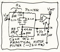
Recently, I had planned on going to an excellent museum. But I wanted to correctly finish the derivation of an equation that had been giving me trouble and wasting a lot of my time, as I had obviously been making errors. This just happens to be the circuit shown in the figure.
I knew what the solution had to be like, but I was getting stupid answers and messy equations that made no sense. So I knew that I had to stop making dumb errors. (The solution I had didn't even have the right dimensions.) I knew the solution had to look very much like:
VOUT = VIN × [1 + 0·pRC + (pRC)2] / [1 + K1·pRC + (pRC)2]
where K1 is some function of k, and pC is the reciprocal of the impedance of a capacitor: pC = j × 2πfC. We also are going to assume that C1 = C2 = C3 = C4 = C, exactly, and that R1 = R2 = R3 = R4 = R, exactly. (Later, we will discuss how to fix things if the Rs and Cs aren't perfect.) We're assuming that the gain and CMRR of the amplifier are plenty high too (and that the gain errors and CMRR errors are small enough and linear enough) at the frequencies you're interested in. Or, if they're not quite small, we will assume we can trim them out.
I wish I could tell you that trimming R1 will trim the center frequency, trimming R3 will trim the depth of the notch, and trimming k will trim the Q, with no interaction. But I can't tell you that, as there's considerable interaction. Still, it's not hard to trim to get good depth and a good center frequency. It may be nice to use 5% capacitors, and it's always reasonable to use 1% film resistors. But nothing fancy is required. In the case where you want 120 Hz, just get 0.01-µF mylars or polypropylenes for Cs, and use R @ 135 kΩ.This works much better than most forms of notch filter. If you need one, this is worth building. I have some other tricks up my sleeve, too. So it's not that I can't do algebraic equations, I just prefer not to—usually. But when it's important, I know how to do them, and I can show you how as well.
I sat in my car in the museum's parking lot, sipping some beer and crunching along on about seven pages of scrap paper. Finally, I came up with the right answer. The above formula was exactly right, and the correct function for K1 turned out to be: K1 = 4 (1 −k).
This means that if k is very close to 1, K1 gets very small, and the Q of this filter is very high (very good). This is much easier to see, in the general case, by using the algebraic equations than by just plugging in the component values. It means that if you have gotten a good notch filter, with the right depth and the right center frequency, you can use the pot at k to trim to get any Q you want without significant interaction. Next time, I will show you how to do the math.
All for now.
This article was published in Electronic Design Oct 1, 2001
see Bob Pease Remembered — One Year Later
This is how Bob always ended his blog. The information is no longer valid.
/ Comments invited!
RAP / Robert A. Pease / Engineer
[email protected]—or:
Mail Stop D2597A
National Semiconductor
P.O. Box 58090
Santa Clara, CA 95052-8090
About the Author

Bob Pease
Bob obtained a BSEE from MIT in 1961 and was a staff scientist at National Semiconductor Corp., Santa Clara, CA, for many years. He was a well known and long time contributing editor to Electronic Design.
We also have a number of PDF eBooks by Bob that members can download from the Electronic Design Members Library.

