For as long as electronics have been around, enclosure engineers have seen their role in the EMC design process as the clean-up crew. Whatever design engineers could not solve with tricks of the trade was left to them to handle. Unfortunately, this practice continues, and an often-repeated process of trial and error to contain electromagnetic interference shows up more often than not in the testing phase.
Problems Caused by Speed
For the design team at one North American OEM, the growth in the internet infrastructure and the accelerating rates in computer processing speeds cause compliance problems. The dilemma centers on the concept of a universal enclosure or cabinet that can be used in applications from single processor servers to a large array of parallel-processing cards.
The old, standard cabinet design had reached its shielding limits with processors running about 400 MHz. A new universal enclosure must handle the current 600-MHz processors and remain functional through the development and implementation of processors running well over 1 GHz.
Although components are changing virtually overnight, the overall dimensions of cabinets, 19″ × 24″ × 74.12″, have not. The interior shell includes bays of subracks that hold the usual assortment of power supplies, cooling fans, processors, and I/O card arrays. A single processor card running at 600 MHz is not much of a problem, but what happens when the enclosure is occupied by 30 cards that are parallel processing at 1 GHz?
Subrack Shielding
For this application, designers started with a cabinet with solid panel sidewalls and bottom and top plates. This left only the front and back of the cabinet susceptible to EMI radiation. The subracks were divided into three compartments with septum shields to provide RF isolation between the different stages of the parallel-processing system. These dividers helped to localize the EMI in the subrack unit that contained the noise source.
To complete the septum shield ground path, gaskets were installed on the front and back of the shield to electrically bond it to the card-guide housing and the backplane. For ventilation, openings punched into the septum shields allowed airflow.
Internal Gaskets
Next, internal gasketing was mounted on the faceplates of the processor and I/O cards rather than on the large door structures at the front and back of the enclosure. The faceplates used clip-on fingers spaced approximately 3″ apart. This followed the OEM’s design standard to keep all slots and openings at or below 1/20th of the fundamental frequency’s wavelength (l), a design rule used throughout the computer and telecommunications industries.
Some companies actually improve on that rule by requiring a slot limit of 1/50th of the fundamental frequency’s wavelength or l/50. The wavelength is calculated using the following formula:
l (meters) = 300/f (MHz)
or
l (feet) = 984/f (MHz)
So, at 600 MHz, l = 0.5 m, and at 2 GHz, l = 15 cm. The fundamental clock frequency may not always be the guilty suspect, since high-speed clock pulses are produced as the sum of the fundamental frequency and the associated harmonics, in particular the odd order of harmonics.
The original cards had processors running around 200 MHz with a wavelength of 1.5 m. The l/20 rule held the slots to 75 mm or smaller, which explained the 3″ spacing of the clip-on fingers.
The new enclosure and faceplate must function to a target frequency of 2 GHz. By using the l/20 rule, the minimum allowable slot or opening was 7.5 mm. Trying to hold the slot dimensions this small ruled out the use of clip-on fingers because of cost and the buildup of compression forces. At 7.5 mm, a gasket must span the entire length of the card and have a lower compression force than a comparable strip of the clip-on gasket.
A conductive fabric-clad-foam gasket, a hollow-core electrically conductive elastomer, and a hollow-core wire mesh were among the solutions considered. The conductive fabric-clad-foam was chosen to shield the faceplate of the card. This decision was based on its low compression-force requirements and the added benefit of improved airflow integrity. By reducing the airflow leakage around the faceplate, a more efficient cooling system was achieved without adding extra fans.
Faceplate Design and Gasketing
The faceplate was constructed out of a machined Series 6000 aluminum. However, the use of aluminum raised concerns about galvanic compatibility. The designers needed a conversion coating applied to the aluminum surface to prevent oxidation of the bare aluminum and degrade the RF joint to the point where it was nonfunctional.
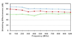
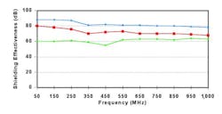
Tests were carried out using modules in a transfer impedance test cell. An alodine-plated aluminum module was compared to a bare aluminum module to see the loss in shielding effectiveness due to the reduction in conductivity across the RF joint (Figure 1, see below). A difference of greater than 20 dB was measured between the two modules.
Figure 1
Another test was run with a module plated with a light chromate conversion coat, often referred to as a clear chromate finish (Figure 1). This module showed some loss in conductivity but maintained a shielding level high enough to ensure that the entire cabinet yielded at least 50-dB shielding over the frequency range of 20 MHz to 2 GHz.
Most EMI gaskets do not have a metal density high enough to provide absorption losses that rival the rest of the metal enclosure. In those cases, the gasket provides losses through reflection of the EMI wave, and the overall shielding performance can be linked to the conductivity or impedance of the gasket material along with the mounting-flange-to-gasket contact resistance. As for the through conductivity of the aluminum card faceplate, selecting a conversion coating that exhibited a minimal loss in transfer impedance helped improve the contact resistance of the gasket to the faceplate flange.
The only other factor in the equation was the gasket’s inherent resistance. The resistance depends on the volume resistivity of the conductive surface and the size of the gasket. The resistance is given as a function of the resistance over a unit length, such as 5 mW/cm.
The general rule: the thicker the gasket, the higher the resistance; the wider the gasket, the lower the resistance. Using these guidelines, the design team selected a fabric-clad 2.8 mm × 9.65 mm gasket. The extra width allowed the use of a gasket that featured two D-shaped profiles formed on a single base. The D-shaped gasket made it easier to insert multiple cards into the cabinet.
Evaluation of the Redesign
Preliminary testing compared the new design of the faceplate shielding to the old style of clip-on fingers. A mockup unit performing parallel processing at 600 MHz was constructed and tested at the OEM’s 3-m test site to FCC Part 15 Class B limits. The tighter Class B limit was chosen because of the headroom that could be obtained over the less stringent Class A limits. This universal enclosure design would end up in a smaller mini-server application that might have to meet the Class B limits.
Figure 2 shows the initial results of the Class B test using the older design faceplate. With only two cards linked in the parallel processing array, the enclosure failed the FCC Class B limits. Figure 3 shows the improvement obtained with the new faceplate design. In these preliminary tests, the unit was approximately 10 dB under the Class B limit.
With this design incorporating both new characteristics and proven estimation techniques, the shielding effectiveness of the universal standard cabinet can be designed with a few new twists. But always remember, a shielding strategy that worked in the past may not work now or in the future-given the speed of change we are all experiencing.
References
- Hemming, L., Architectural Electromagnetic Shielding Handbook, IEEE Press, 1992.
- Malon, M.J., Printed Circuit Board Design Techniques for EMC Compliance, IEEE Press, 1996.
- Ott, H.W., Noise Reduction Techniques in Electronic Systems, John Wiley & Sons, 1988.
About the Author
Shane Hudak is the EMI product manager at Schlegel Systems, a member of the UniPoly group of companies. He has more than 10 years of experience in EMC test and measurement and EMI shielding strategies. Schlegel Systems, 1555 Jefferson Rd., P.O. Box 23197, Rochester, NY 14692, (716) 427-7200.
Published by EE-Evaluation Engineering
All contents © 2000 Nelson Publishing Inc.
No reprint, distribution, or reuse in any medium is permitted
without the express written consent of the publisher.
January 2000

