While there always has been a need for load board verification, the trend toward surface-mount technology (SMT) has amplified the need. IC test sockets with spring probes have added a significant electromechanical interface to the test interconnect assembly, with an increased potential to adversely affect IC package test accuracy and reliability.
Ideally, the load board provides an essentially transparent mechanical and electrical interface between the IC and the ATE. This allows accurate and reliable verification of IC circuit integrity and performance.
Testing a load board to verify continuity before it is used to test an IC can save time and money. For example, there is no way to know that a failure indication during initial test really is the result of a defective IC unless you have first verified performance of the load board.
It takes time to determine whether an IC failure during test was genuine or the result of a faulty load board. With test time running from $400 to $500 per hour, after-the-fact verification can easily cost thousands of dollars annually. Even load boards that have performed well in the past can fall victim to an inevitable life-cycle failure, which makes periodic reverification of the load board as important as initial verification.
Load Board Verification
Three primary methods can verify load board performance. The most basic is manual verification. In this form of testing, an ohmmeter checks for shorts or opens between the test socket-to-IC contacts and the PCB-to-ATE contacts.
While this method of testing is quite limited, it can be cost-effective for low pin-count devices, typically fewer than 50. However, this test method is neither practical nor cost-effective for advanced designs that feature hundreds of contacts.
At the other end of the spectrum, you can use the same million-dollar ATE you use for device testing to verify the load board. This method is costly and inefficient and can waste valuable test resources. Even if the ATE is not fully used for IC testing, special software may need to be written and other accommodations made to facilitate load board verification.
A third method uses a dedicated load board test system. It usually offers advantages in cost over using ATE and in time and reliability over manual testing.
As with manual or ATE load board verification, a dedicated test system measures resistance and leakage currents to verify that there are no opens or shorts in the interface circuitry. A dedicated system, such as the Cerprobe BOSS Load Board Test System, measures circuit resistance, leakage currents, and capacitance and compares these measurements against established parameters.
Resistance can be tested over a range from 1 mW to 100 MW, typically at 0.1% accuracy and 0.1% resolution. Leakage can be tested over a range from 10 nA to 100 µA, typically at 1% accuracy and 0.1% resolution. Capacitance can be tested over a range from 10 pF to 10 mF, typically at 5% accuracy and 0.1% resolution. Typical load board resistance is less than 100 mW, typical leakage is less than 100 nA, and the capacitance depends on the number and values of capacitors mounted on the load board.
The test system also verifies the performance of numerous configurations of rectifier diodes, zener diodes, and transorbs. In addition, system options can accommodate testing of relays (user-specified relay armature voltages) and high-voltage components (up to 35 V) that may be incorporated into the load board circuitry.
A frequently asked question is whether impedance is or should be tested as part of the load board test. Impedance and propagation delays are a product of the DUT board design and tested using a time-domain reflectometer as part of the DUT board design process.1
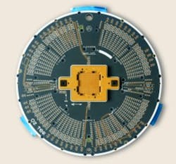
An important characteristic of a dedicated load board test system is the flexibility it provides in emulating various test heads. It must offer a variety of test-head simulators to reliably verify performance of load boards for different ATE models.
The flexibility and versatility of a test system directly relate to the speed and ease with which one test-head simulator can be replaced with another. Because a dedicated test system is located in a manufacturer’s maintenance facility rather than on the test floor, tools and other diagnostic equipment are within reach, providing an additional timesavings.
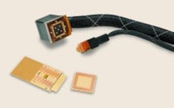
A dedicated load board test system also offers different simulation options. A probe can be inserted into a contactor or test socket to provide a point-to-point resistance test between the socket contacts and the PCB test-head contact points. This method verifies proper socket-to-PCB termination, especially important when the socket is wired to the PCB.
An additional application of a dedicated load board test system is the evaluation and replacement of spring contactors in the SMT sockets. By using a contact resistance (Cres) fixture, the SMT interfaces can be evaluated prior to being attached to the load board. The Cres fixture also allows off-line identification and replacement of faulty spring contactors.
There are several advantages of a system where the hardware and the software are designed for load board test and verification. The type, range, and tolerance of measurements specifically address critical test parameters, and hardware/software setups are tailored for quick and easy conversion from one test simulation to another. Offset capabilities allow for nullification of fixture resistance, leakage, and capacitance that could affect measurement accuracy when testing the load board.
Software compatibility with standard computer operating systems and database applications enables collection and storage of all measurements to create a complete test history. The data-storage capability is extremely powerful since elements of the test history can be used to establish baseline measurements. The baseline data then can be compared and analyzed with subsequent test measurements to project operational trends and determine board repair and replacement schedules.
Conclusion
As semiconductor designers continue to produce ICs that cram more circuitry into smaller areas with higher pin-counts and tighter pitches, verifying IC package performance, will only become increasingly demanding. Verifying the load board before using it for IC testing will save time and money.
Using a dedicated load board test system also verifies the performance of a variety of different load board configurations with a wider range of measurement capability. Finally, it will allow storage and comparison of the measurement data to determine board repair and replacement schedules.
Reference
-
Barabi, I., “Designing DUT Boards for IC Test,” EE-Evaluation Engineering, August 1999, pp. 64-71.
About the Author
Larrie Osteros is the general manager of Cerprobe’s Load Board and Burn-In Board Test Systems Group. He has more than 16 years experience in the design and production of load board and burn-in board test systems. Mr. Osteros majored in electrical engineering and business management at the University of Maryland. Cerprobe, 1150 N. Fiesta Blvd., Gilbert, AZ 85233, 877-333-2772, email: [email protected].
Return to EE Home Page
Published by EE-Evaluation Engineering
All contents © 2000 Nelson Publishing Inc.
No reprint, distribution, or reuse in any medium is permitted
without the express written consent of the publisher.
August 2000


