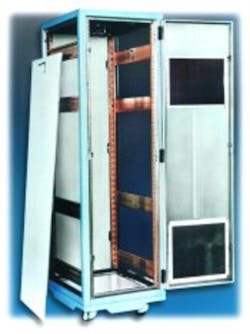
Your product design is underway, and you expect to have a prototype completed in two months. That will be soon enough to start thinking about EMC, and a good enclosure will solve all of your EMC problems. Right? Absolutely not. The enclosure is an integral part of your product, and the time to choose an enclosure is at the very beginning of the design cycle.
The best enclosure in the world is only marginally effective if you don’t start by incorporating good EMI and RFI control practices at the component and subassembly levels. The corollary is that the best control practices in the world are only marginally effective if you don’t have a good enclosure and use suitable gasketing. It all goes together to give you a high quality product.
Allowable Interference Levels
To begin, you must set goals for EMI control and fully define your governing standard. For example, the Federal Communications Commission (FCC) has established limitations on conducted and radiated interference levels for computers and related equipment by classes. For Class A devices used in commercial or business applications, the regulation specifies the maximum allowable emanations at a 30-m distance for several frequency ranges. Other classes of equipment and other agencies require similar test conditions but different limits.
Designing for Success
RF control must come early in product design. Containment of radiation at the lowest subassembly is possible and has become increasingly important since this is the most effective and least expensive point of control. Reducing wire count and lengths will help, as will attention to grounding and impedance matching on the backplanes and cables.
Michael Long, the standard product manager at Tracewell Systems, offers a few suggestions to reduce EMC problems in your equipment while minimizing cabinet costs and staying on schedule:
- Develop a thorough definition of the application and the operating environment. This allows you to select techniques that meet your needs but are not too expensive and can be implemented in time to meet your deadlines.
- Define the location of your expected EMI/RFI emitters, both internal and external, and the probable strength of each. Where are the receptors, and what levels of RF can they safely tolerate? What are the frequencies of concern? Are there significant harmonics? Can some degree of containment or protection be designed into the PCBs, backplane, and power supplies less expensively than depending on the enclosure to do most of the job?
- What access does the user need for normal operation of the product? It may be possible to build an enclosure with integral shielding that is part of the sheet-metal structure. For example, sheet metal can be formed to act as a waveguide at microwave frequencies and minimize radiation at the enclosure joints.
- Beyond the physical chassis, what boards and cabling will be installed in the system? What are their EMC characteristics?
The Equipment Enclosure
If EMC were the only criterion in electronic system design, the ideal enclosure would be a spherical metal container with no seams or openings. However, this would be of no value because you need openings for equipment operation.
The objective in equipment design, then, is to make an optimum compromise between the impractical ideal and the real world. You must bring power in, route signals in and out, dissipate internally generated heat, monitor equipment operation, access the internal subassemblies for adjustment or repair, and yet preserve the EMI/RFI shielding almost as well as if you had that ideal enclosure.
A closed door on your cabinet can be made relatively impervious to RF leakage. First, the removable panel or door and the matching opening must be rigid so that when closed the seams are leak-proof. Also, the surfaces that touch must be unpainted and galvanically compatible to ensure that no corrosion will develop. Then gaskets can be installed to make a good shield whenever the cabinet is closed.
A viewing hole can be made relatively EMI-proof with a metallic wire mesh or a thin perforated sheet bonded between layers of glass, acrylic, or polycarbonate. For better transparency but somewhat less EMI protection, glass with a conductive coating of vacuum-deposited gold or indium oxide will do the job.
Perhaps the most challenging selection is a vent for the air circulation system. You want air to flow in and out of your enclosure with virtually no difficulty, but you have to be concerned about EMC and would prefer no RF leakage at the vents. The two goals are contradictory, but a cabinet manufacturer can help you find an acceptable compromise.
“If you require a significant amount of forced-air ventilation, metallic air filters, mesh screen, or honeycomb can allow flow, keep contaminants out of the system, and restrict the entry or exit of EMI,” explained Mr. Long of Tracewell Systems. “Possibly high-pressure air movement or the use of additional cooling equipment will be necessary.”
To know if a properly designed cabinet with provision for air flow, windows, and cable entry will solve potential EMI problems, Mike Herzog, the industrial product line manager at Rittal, suggests that you choose an experienced enclosure specialist. Then the two of you need to answer these questions:
- Will the expected interference be transmitted through free space or the cabling? An enclosure can be selected to address the free-space problem, but you will need other techniques such as line filters or chokes to solve a leakage problem in the cabling.
- What is the nature of the expected EMC problem? A good enclosure can help solve electrical and electromagnetic interference. Magnetic problems, on the other hand, will require a very thick, highly permeable material such as mumetal or iron.
- What level of protection will be needed and for what frequency range?
- Can you use a standard enclosure? If not, can an enhanced standard product do the job? A standard enclosure will save money. However, sometimes the shielding effectiveness of a standard enclosure can be improved by as much as 20 dB by installing off-the-shelf accessories from the same supplier at a cost of perhaps no more than $100.
If the potential for EMC problems is too severe for low-cost solutions, determine whether a custom enclosure will do the job. Possibly you will require a customized cabinet plus judicious use of component and cable shielding.
Apertures Are Necessary But Leakage Is Optional
Even after careful decisions about equipment design and cabinet selection, you must augment the RFI control by drawing the line on the size of apertures. RF energy, internally or externally generated, causes a current flow in the metallic skin of the enclosure. At low frequencies, the current presents no difficulties at the apertures. It simply detours around them.
But, we don’t live in a low-frequency world. Virtually every new product pushes the frequency frontiers, and this creates problems at the apertures of the enclosure. Shorter switching times and steeper pulse edges cause high-frequency currents. They can’t take detours, and voltage builds up across the openings. The voltage goes up as the wavelength (l) goes down. When the length of an aperture approaches 0.5 l, the aperture begins to resonate. Energy is propagated, and you have a classic EMC problem.
You can predict the performance of a given size slot on your product. To be realistic, look at the harmonics of your basic operating frequency. A good rule of thumb is to expect significant harmonics five times your fundamental operating frequency. Instead of 0.5 l, the greatest dimension of an aperture should be limited to 0.1 l. This is 30 cm at 100 MHz and just 3 cm or less than 1.2² at 1 GHz.1
An EMC Test Standard
Applying the best known control techniques for enclosures is only a part of the battle against unwanted EMI. Perhaps the time is right for the industry to develop some international standards for measuring electromagnetic interference related to enclosures. Such procedures could be of great value in determining the effectiveness of your equipment.
“During the Cold War,” according to Lou Gnecco, president of Tempest, “the biggest users of EMC test equipment were the U.S. government and its contractors. To protect the integrity of the testing programs, the National Security Agency (NSA) tightly controlled this technology. Document 65-6 specified shielding performance and included assembly specifications, design objectives, enclosure reliability, and filter requirements. It explained the test arrangement in great detail and left nothing undefined.
“Now the Cold-War urgency is gone,” Mr. Gnecco continued, “and the present-day thrust relates to the wireless revolution and EU requirements. The NSA document is not appropriate for today’s technology, and an internationally recognized testing standards and certification program is needed.”
Reference
- Violette, M. “The 10 Basic Steps to Successful EMC Design,” EE-Evaluation Engineering, January 1998, p. 75.
Return to EE Home Page
Published by EE-Evaluation Engineering
All contents © 2000 Nelson Publishing Inc.
No reprint, distribution, or reuse in any medium is permitted
without the express written consent of the publisher.
September 2000

