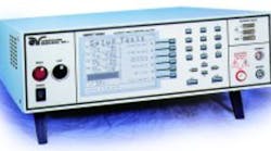
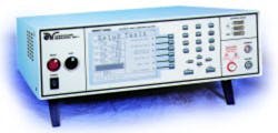
New safety-related features are made possible by the latest microprocessors and software, including faster shutdown speeds, multiple failure-detection networks, no-load setting of trip-current levels, and the ground-fault interrupter (GFI) circuit. Each of these safety features protects the operator and reduces shock hazard.
Perils of the Past
Most old analog-style hipot testers contained few safety features. The analog designs didn’t easily lend themselves to simple safety improvements, and component costs drove manufacturers away from incorporating changes.
Some of these testers did not shut off the high-voltage circuit when the current trip setting was exceeded. Instead, they incorporated high-reactance transformers, which were current-limited. The voltage collapsed, and the current was limited to a short-circuit current, typically less than 15 mA. Yet these currents are considered dangerous by today’s standards.
Currents between 5 mA and 10 mA can paralyze an operator. Currents in the range of 20 mA to 40 mA between the extremities cause the muscles to contract painfully, making breathing difficult and often leading to asphyxiation. Current levels in the 40-mA to 70-mA range for 1 s or longer bring about ventricular fibrillation, which frequently is fatal.
To set the voltage output and current trip settings on older analog hipots, the operator had to make adjustments while the high voltage was on, using load resistors and an external current meter to get the desired reading. The output was adjusted until the high-voltage circuit shut down or a warning lamp or buzzer activated. Generally, this process had to be repeated several times.
Today, a major benefit of microprocessor control is the no-load setup feature. Now all parameters are adjusted digitally through a menu-driven software program without the need to activate the high voltage. This technique is much safer and more accurate than the older method.
Modern Failure-Detection Networks
To further reduce the shock hazard inherent when using high-voltage instruments, a hipot tester should incorporate several failure-detection networks with fast shutdown speeds to protect the operator. Four different networks can achieve acceptable results.
High- and Low-Current Sensor
The high- and low-current sense circuit is an adjustable current detector with a typical shutdown speed of about 400 ms. The high-current sensor permits the operator to set a maximum allowable leakage current for the test, and the low-current sensor accommodates setup of a minimum leakage current to ensure that the test was performed on the device under test (DUT).
If the current level is between these minimum and maximum levels during a test, the DUT passed. If the hipot detects current below the minimum during the test, it gives a failure signal. This signal tells the operator that the current dropped below the required minimum level, causing a failure condition. For example, this could mean that a test lead came off the DUT.
Overload Sensor
The second failure detection network is an interrupt circuit. The speed with which this overload detector shuts down the high voltage is very important in protecting the operator. In the past, if the operator received an electrical shock while performing a hipot test, he was in contact with the high-voltage source when the test started. The other possibility is that there was a high-voltage arc, even though the operator didn’t come in contact with the source.
The overload detector uses a hardware set point that is adjusted for a value slightly higher than the maximum current capacity of the instrument. If this value is exceeded, an interrupt signal is fed to the microprocessor within 400 µs to shut down the high-voltage circuit.
Arc Detector
An arc detection circuit, the third failure-detection network, incorporates a high-pass filter circuit that only responds to frequencies greater than 10 kHz. These high-frequency signals are fed into a comparator and checked against the user-selected sensitivity level. If this level is exceeded, an interrupt signal is fed into the CPU, which shuts down the hipot in about 400 µs.
Ground Fault Interrupter
The fourth and latest safety feature is a smart GFI. This circuit is based on the same principle as the familiar household interrupter that trips and shuts off an appliance when the current flowing through ground exceeds a predetermined level. In the home, this protection circuit is located in areas of increased safety risk such as the bathroom, kitchen, and basement. It also is used on portable power tools.
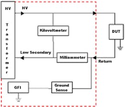
When performing a high-voltage test, the DUT should be isolated from ground, but this is not always practical. If the DUT is grounded, the GFI circuit must be turned off or the hipot will signal a fault condition because it senses the leakage current through the ground return as shown in Figure 1 (see below).
Figure 1. Hipot Tester with the DUT Grounded
The smart GFI in a hipot tester should have a sensing circuit that opens, disabling high voltage when excessive current flows to ground. The smart circuit senses whether the DUT is in a floating or a grounded configuration. It also senses the DUT’s configuration and turns itself on or off automatically.
The smart GFI is truly safe because the operator has been completely eliminated from the equation. It always is enabled and works transparently. Any such circuit is active only if the DUT is floating and the hipot is using a floating-return configuration.
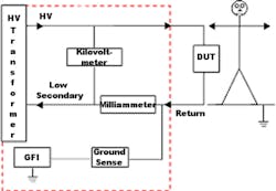
The main purpose of the interrupter is to protect the operator from prolonged exposure to high voltage in case of accidental contact. The circuit should trip in a short period of time if the current flowing to ground exceeds some very low current limit, such as 450-µA AC or DC in less than 1 ms, as shown in Figure 2.
Figure 2. Hipot Tester Without the DUT Grounded
The shutoff point is independent of the leakage-current limit setting on the hipot. It provides maximum protection to the operator in the presence of high voltage.
Most manufacturers of electrical or electronic products follow safety-agency guidelines and appropriate safety standards to ensure that the products they produce are electrically safe. Manufacturers also have the obligation to provide an equal level of protection to their operators who perform these hipot safety tests.
About the Author
Dwayne M. Davis is the technical services manager at Associated Research. For more than 30 years, he has been involved in the design, development, and manufacture of high-voltage products including transformers, power supplies, and safety testing instruments. Mr. Davis holds a degree from DeVry Technical Institute. Associated Research, 13860 W. Laurel Dr., Lake Forest, IL 60045, 847-367 4077, e-mail: [email protected].
Return to EE Home Page
Published by EE-Evaluation Engineering
All contents © 2001 Nelson Publishing Inc.
No reprint, distribution, or reuse in any medium is permitted
without the express written consent of the publisher.
May 2001


