Click To View BenchTop DMMs
Specification table.How accurately do you need to measure an unknown resistance? Is it enough to know that a resistor??s value is greater than 1 MW, or must you know the value to five decimal places? The answer determines the measurement cost and the technique that should be used. A basic hand-held DMM is easy to use and quickly provides a reading accurate to a few percent. Benchtop DMMs can supply 0.001% accuracy. Calibration lab measurements with <1-ppm uncertainty are referred to standard resistances immersed in constant-temperature oil baths that take hours to stabilize. Regardless of the required accuracy, most measurement techniques apply a DC voltage across the unknown resistance and measure the resulting current, or they apply a known DC current through the resistance and measure the resulting voltage across it. The value of the resistance affects the practicality of either approach.For example, when measuring very small resistances, a large current must be sourced or the resulting voltage across the DUT may be too small to be accurately measured. Unless the voltage can be made larger, noise and offset within the measuring system will limit the achievable accuracy. On the other hand, a higher current causes greater self-heating, which changes the DUT resistance. Some microohmmeters have a 10-A test current.Similarly, to avoid measuring a very small current, some DMMs apply 100 or 200 V across large resistances. In this case, errors will include any value changes related to the resistance??s voltage coefficient. Megohmmeters provide test voltages of 500 V and higher for applications such as insulation testing.To improve accuracy, regardless of which approach is used, the forcing circuit must be separated from the measuring circuit. The basic two-wire ohms circuit is a good example of combined circuits. The voltage measurement includes the potential drops caused by the forcing current flowing through the connecting wires as well as the DUT. Consequently, the wire resistance adds to the DUT resistance. Using a Kelvin four-wire connection avoids this problem by providing separate current-forcing and voltage-measuring circuits. Because the voltage-measuring instrument has high input impedance, negligible current flows in the voltage leads, and a much more accurate measurement of the DUT resistance results.An Example
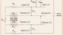
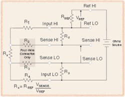
In the Keithley Models 2701 and 2750 DMMs, a constant current source is used with voltage sensing for resistance measurements below 1 MW. Above this level, a ratiometric voltage-driven circuit is used, as shown in Figure 1. The value of the reference resistance RREF is accurately known. Because Ref LO, Sense HI, and Sense LO are connected to high-impedance inputs, the same current that flows through RREF also flows through the unknown resistance RX. Therefore, the value of RX can be determined by a simple computation:
RX = RREF *
Ref Hi – Ref LO
VREF
Shunting Resistances
In production test applications involving resistance measurement, it??s not unusual for shunt paths to exist. For example, other resistors are physically connected across the DUT in many styles of level-shifting or terminating resistor networks. A less obvious and variable shunt resistance is formed by contamination that gradually builds up across the test-fixture contacts of a component handler. To eliminate the measurement errors caused by shunt paths, a six-wire ohms technique is used. In this approach, the shunt path is driven by a guard voltage that is nearly equal to the voltage at the high side of the DUT. For resistor networks, a suitable node is driven. Production test fixtures must have a separate guard electrode added between the high and low contacts. In both cases, because the shunt path and the DUT high terminal are held at nearly the same voltage, negligible current flows in the shunt path, and measurement accuracy is greatly improved.
Voltage Offsets Associated With the DUT
Depending on the type of application, many sources of voltage offset may contribute to resistance measurement errors. For example, accurate human-skin resistance measurements are difficult to achieve because naturally occurring salts and moisture on the skin produce an offset voltage when a probe is attached. Another commonly encountered but much smaller voltage source results from the test current flowing through junctions of dissimilar metals in the measurement circuit.
Figure 1. Ratiometric Measurement Circuit
Source: Keithley InstrumentsIf the connections to the DUT are reversed, the effect of the offset voltage also reverses. So, by making pairs of forward/reverse measurements and averaging the results, voltage offset errors can be eliminated. This is a well-understood procedure in a standards lab. ??Once the [standard] resistor has been acclimatized (generally at least 24 hours) and properly connected, measurements can begin. Current through junctions of dissimilar metals will generate thermal EMFs by the Peltier effect; one junction will heat and the other will cool. Reversal of the measurement current reverses the Peltier effect. Averaging these reversed readings provides an arithmetic cancellation of thermal offsets that may lurk in the system. Averaging a series of 10 or 20 reversed readings will give a higher degree of confidence in the measured value.??1 Fluke calls this mode of operation Tru-Ohms. Keithley simply refers to it as a DC current-reversal technique and stresses the difference between this method and conventional offset compensation that involves two measurements made with different magnitude currents of the same polarity. Traditional offset cancellation schemes reduce the value of the current source to nearly zero and measure the voltage across the unknown resistance. This measurement is approximately equal to the offset voltage. Subtracting this value from the voltage measured with the full test current will eliminate voltage-offset errors to a large extent. Of course, if the offset or the DUT resistance depends on the test-current level, cancellation will only be partially effective. Self-Heating Caused by the Test Current
The best way to reduce DUT self-heating is to decrease the test current. Power dissipation goes as the square of the test current, so self-heating caused by a test current that has been reduced to 10% of its original value is only 1% of the former level. Reducing test current as much as possible is very important when dealing with resistance temperature devices (RTDs), typically platinum 100-W resistors used to measure temperature. Unfortunately, decreasing the test current also reduces the signal-to-noise ratio. The signal of interest has become much smaller, but the system noise level has remained constant. Filtering to reduce the measurement bandwidth is an effective way to reduce random noise. However, thermal EMFs and errors caused by drift are the largest noise sources at very low frequencies, and they are not filtered out. If a pair of forward and reverse measurements is taken very quickly, the DUT temperature will not have sufficient time to change, and drift-induced thermal EMF errors can be avoided. For example, suppose you needed to accurately determine the resistance of a nominal 1-W resistance using a 100-??A test current to limit self-heating. A voltage sensitivity of 10 nV is required to achieve 0.01% resolution. If the DUT is connected to the measuring system through copper to tin/lead connections, thermal EMFs of 1 to 3 ??V/??C are typical. To maintain the DUT voltage measurement to within 10 nV requires that the temperature be held constant within 0.003??C. Drift will occur if the forward and reverse measurements are significantly delayed from each other.2 ??Understanding and reducing thermal EMFs is particularly important when using a precision DMM to measure platinum resistance thermometers,?? said Peter Dack, Fluke precision measurements marketing manager. ??The Tru Ohms reversal technique helps, but so does ensuring that the constant current being generated through the resistance, typically 25 W to 100 W, is as low as possible. The Fluke Model 8508A has selectable current settings for this reason.?? Another approach to this problem uses an AC measurement technique rather than DC. ??AC excitation operates similarly to the chopping scheme used in precision amplifiers; in transducer signal-conditioning circuits, it removes offset errors, averages out
1/f-noise, and eliminates effects due to parasitic thermocouples. With decreased sensitivity to 1/f-noise, a discernible output signal can be produced with much lower excitation current or voltage.??3 The Lake Shore Cryotronics Model 370 AC Resistance Bridge uses this technique. According to the company, the benefits of AC excitation include greater sensitivity, which results from higher gain than is practical with a DC system. Further, phase sensitive detection, an AC filtering technique used in lock-in amplifiers, can be used to reclaim small measurement signals from environmental noise. For example, 0.03% accurate resistance measurements are specified for the Model 370 on its 20-W range, which uses a 10-??A test current and has 300-??W resolution. In contrast, although the accuracy of the Fluke 8508A??s 20-W range is in the region of 0.001%, the DC test current is 10 mA—1,000 times higher. Similarly, the Keithley Model 2750 DMM uses a 1-mA DC test current on its 10-W dry-circuit range to provide 10-??W resolution and about 0.05% measurement accuracy.Summary
If worrying about the effect of barometric pressure changes on the lattice structure of your Manganin or Evanohm standard resistors is keeping you awake nights, help is on the way. Between 2005 and 2007, researchers in the National Institute of Standards and Technology??s (NIST??s) national electrical standards program hope to have developed an extremely accurate resistance. They already can accurately determine the current produced by a single-electron tunneling (SET) device, but this current is too low to use in directly closing the so-called metrology triangle. This phrase refers to a high-accuracy realization of Ohm??s law with voltage, current, and resistance each being referred to intrinsic quantum phenomena: voltage to Josephson array voltage standards, current from single-electron pumps, and resistance from quantum Hall resistance standards.For the large majority of engineers who have accuracy requirements in the 1% to 0.001% range, many models of DMMs are available now, as listed in the comparison chart that accompanies this article. Your detailed application needs and budget constraints are the two most important criteria to apply when making your choice. It??s especially important to examine the product??s specifications in detail so that the effect of the instrument on the DUT is well understood.References
1. Klevels, J., ??Standard Resistors: Their Use and Maintenance, an Overview,?? Process Instruments, http://www.leeds-northrup.com/callabmagarticle.htm
2. Miller, C., Techniques for Reducing Resistance Measurement Uncertainty: DC Current Reversals vs. Classic Offset Compensation, Keithley Instruments, 2000, www.keithley.com/servlet/Data?id=4644
3. O??Grady, A., ??Transducer/Sensor Excitation and Measurement Techniques,?? Analog Dialogue, 34-5, 2000.
4. ??Single Electron Tunneling,?? http://www.eeel.nist.gov/811/electron.html
Return to EE Home PagePublished by EE-Evaluation Engineering
All contents ?? 2004 Nelson Publishing Inc.
No reprint, distribution, or reuse in any medium is permitted
without the express written consent of the publisher.

