A reliable method predicts code spurs so unwanted spurs can be positioned to project onto unused codes
The capability to predict the spreading codes of code spurs generated by transmission nonlinearities can provide significant benefits in code division multiple access (CDMA) system operation. Typical nonlinearities that create code spurs are downlink (forward-link) signal compression or deliberate signal clipping, the latter being widely used to improve amplifier headroom.
A method has been devised for predicting code spurs where, through careful choice of active codes, it is possible to position unwanted spurs to project onto unused codes in the code domain rather than onto the active codes upon which system performance depends. The modulation quality of the codes then can be optimized, leading to improvements in link efficiency.
By using a code-channel allocation algorithm based on code-spur prediction, more aggressive signal clipping can be used. This reduces the required headroom of the power amplifier without degrading system performance.
By evaluating the resulting downlink signal using error vector magnitude (EVM) on the active codes, such as the EVM of the symbols of each de-spread code channel, the traditional measurements of EVM and peak code domain error (PCDE) on the composite signal can effectively be ignored. The net effect allows the system to be operated in conditions previously considered unacceptable due to the unpredictability of the code spurs.
How Are Code Spurs Generated?
The principle defining the generation of code spurs in the code domain is similar to the well-known mechanism that occurs in the frequency domain. When two sine waves at different frequencies (f1 and f2) are linearly added, the frequency domain will contain only the original frequencies.
However, if the two signals are allowed to pass through a nonlinear transformation such as an amplifier in compression, the signals will multiply, producing new frequency components. The most problematic frequency components are the third-order intermodulation products at 2f1 – f2 and 2f2 – f1.
In an ideal CDMA transmitter, the generation of the composite signal is the result of a linear addition of the spread channels. However, intermodulation distortion products will be generated in the code domain if the transmitter is operating in compression or uses clipping, such as deliberate distortion, to improve headroom.
Until now, it generally has been assumed that the vector product of any two spreading codes of the same length will multiply to create a new third signal or code spur. However, this assumption is too simple and cannot be used as a basis for predicting code spurs.
Code-Spur Prediction
Most practical CDMA composite signals contain many codes at various spreading factors and code-domain powers. As a result, developing a method for predicting where code spurs will occur is difficult.
While there is a strong relationship between the number of active codes and the number of code spurs, there is no intuitive way to predict the exact number and position of code spurs. However, a general rule describes the relationship between active codes and the code spurs generated by transmission nonlinearities.
Generally, code spurs will be generated whenever a composite signal containing energy in three or more codes from the same orthogonal set (at the same spreading factor) is passed through a nonlinear function, such as amplitude clipping or amplifier compression. One code spur will be generated for every permutation comprising an odd number of at least three active codes that can be chosen at the same spreading factor from the composite signal. The spreading code of the code spur will be the vector product (assuming bipolar notation) of all the spreading codes in each permutation, and the code spur will have the same spreading factor as the codes used in each permutation.
Two special cases must be considered:1. If the vector product of an odd number of at least three spreading codes at the same spreading factor results in a code of all ones (i.e., predicting Cn(0) where 2n is the spreading factor and Cn(0) is code number zero with that spreading factor), then, for that permutation, no discrete code spur will be produced.2. If the composite signal contains spreading codes from more than one orthogonal set, such as multiple spreading factors, lower-order active codes must be substituted by the higher-order codes that occupy the same space in the code domain. This substitution must be carried out at all the spreading factors present in the composite signal at which active codes exist. After code substitution at these active spreading factors, the code spurs for those factors can be calculated using the general rule and special case 1.
| # of Active Codes | Permutations | Total # of Code Spurs | Total # of Codes | |||
| 3 Codes | 5 Codes | 7 Codes | 9 Codes | |||
| 1 | 0 | 0 | 0 | 0 | 0 | 1 |
| 2 | 0 | 0 | 0 | 0 | 0 | 2 |
| 3 | 1 | 0 | 0 | 0 | 1 | 4 |
| 4 | 4 | 0 | 0 | 0 | 4 | 8 |
| 5 | 10 | 1 | 0 | 0 | 11 | 16 |
| 6 | 20 | 6 | 0 | 0 | 26 | 32 |
| 7 | 35 | 21 | 1 | 0 | 57 | 64 |
| 8 | 56 | 56 | 8 | 0 | 120 | 128 |
| 9 | 84 | 126 | 36 | 1 | 247 | 256 |
| 10 | 120 | 252 | 120 | 10 | 502 | 512 |
Table 1. Permutations of Codes Creating Code Spurs
Typical examples of the numbers of code spurs for different numbers of active codes in the same orthogonal set are given in Table 1. The total number of codes (active plus spurs) always equals 2m-1, where m is the number of active codes.
However, in most circumstances, the code spurs will fall not just on unused codes but on used codes or other code spurs. Due to overlapping codes, the total number of code spurs visible in the code domain often will be less than the number indicated in Table 1.
Predicting the Code-Domain Power
The code-domain power of any spur is a function of a number of variables including the power of the active codes in each permutation, the number of codes in the permutation, and the nature of the nonlinearity. In particular, spurs generated from triplets of codes are 10 dB higher than spurs generated by quintuplets of codes, with higher-order spurs small enough to ignore. Since the level of active codes is never constant due to power control, an average must be used to analyze typical signals.
Using Exclusive OR
A more convenient way to calculate code-spur spreading codes does not require calculating the vector products of long spreading codes. Performing an exclusive OR operation on the binary representation of the code indices of any one orthogonal set generates the index number in that set of the vector product of the two spreading codes.
This relationship holds for both the Hadamard numbering of the Walsh codes in IS-95 and CDMA2000 as well as the bit-reversed Hadamard code numbering used in wideband CDMA (W-CDMA). In general, the index of the code spur produced from the codes Cn(x), Cn(y) and Cn(z) is given by x Å y Å z.
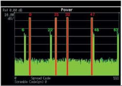
For example, consider the signal in Figure 1.
Figure 1. C6(9), C6(25), C6(32), and C6(47) With 50% Clipping Plus Four C6 Code Spurs
The active channels are C6(9), C6(25), C6(32), and C6(47). If the general rule is applied, with four active codes, there are four permutations of three codes that will multiply to predict code spurs (Table 1). The four permutations of three active codes are the following:
C6(9), C6(25), C6(32)
C6(9), C6(25), C6(47)
C6(9), C6(32), C6(47)
C6(25), C6(32), C6(47)
The code-spur code index can be calculated by performing an exclusive OR operation on the indices of the codes in each set. As a result, the code spurs can be predicted as follows:
9 Å 25 Å 32 = (001001 Å 011001) Å 100000 = 010000 Å 100000 = 110000 = 48
9 Å 25 Å 47 = 010000 Å 101111 = 111111 = 63
Similarly, 9 Å 32 Å 47 = 6 and 25 Å 32 Å 47 = 22. These results match the code spurs shown in the code-domain display in Figure 1.
Permutations of even numbers of codes do not multiply to produce spurs on other codes. In Figure 1, the vector product of the codes C6(9), C6(25), C6(32), and C6(47) would predict C6(31), but no such code spur exists. This is an essential principle that must be followed if correct algorithms are to be developed to predict the spreading codes of code spurs.
Example of Handling Multiple Spreading Factors
When dealing with more than one set of orthogonal codes (more than one spreading factor), special case 2 must be applied. Because this signal contains codes from more than one spreading factor, we cannot directly calculate the code-spur positions without first substituting codes according to special case 2.
In a composite signal with active codes C4(9) and C6(17), spreading codes 32, 33, 34, and 35 from the same orthogonal set C6 replace C4(9). In other words, the code domain of the composite signal has been represented using codes from only one orthogonal set, in this case spreading factor 26 or 64.
The code powers of the C6 channels must be 6 dB lower than the original C4 channel so the integrated power of the four C6 channels adds up to the same power as the original C4 channel. It now is possible to apply the general rule to calculate the position of the C6 code spurs, which occur on C6 indices 16, 17, 18, 19, 32, 33, 34, and 35. As a result, five of the eight predicted spurs fall on other active codes.
This example involved two sets of codes and generated eight spurs. When there is a mixture of three or more higher-order and lower-order codes, the substitution process quickly fills up the code domain. Nevertheless, this does not invalidate the concept that it is better to predict where codes spurs will fall rather than assume they are too numerous to deal with.
A Seven-Code Example From W-CDMA
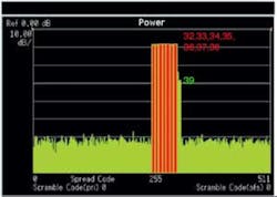
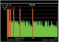
In Figure 2, a seven-code signal with 50% clipping shows only one visible code spur at C6(39) that, for subsequent discussion, will be called the adjacent-channel allocation. Now consider an alternative channel allocation of the spreading codes (Figure 3).
Figure 2. C6(32), C6(33), C6(34), C6(35), C6(36), C6(37), and C6(38) With 50% Clipping
Figure 3. C6(0), C6(1), C6(2), C6(4), C6(8), C6(16), and C6(32) With 50% Clipping
On first inspection, by considering only the code-domain power analysis, the adjacent-channel allocation in Figure 2 seems to be much better in terms of code spurs. However, by looking closer at these two composite signals and considering EVM, a very different picture emerges.
Despite only one code spur being visible at C6(39), the adjacent-channel allocation signal is severely distorted with an EVM of 25.36% against a system specification of 17.5%. The PCDE is -21.95 dB compared to a requirement of less than -33 dB.
In contrast, the signal with the alternative channel allocation shows better but still marginal performance: The EVM at 16.69% and PCDE at -34.82 dB are both just inside the W-CDMA system specifications. This analysis of the quality of the two composite signals shows more degradation of EVM and PCDE for the adjacent-channel allocation. Mainly, this is the result of a secondary effect caused by the adjacent-channel signal having a higher peak-to-average ratio than the alternative-channel allocation and more affected by 50% clipping.
The real difference between the two signals and the advantage of the code-spur prediction method can be seen only when considering the EVM of the individual code channels at the symbol level. A summary of the average symbol EVM on each code for the two signals is shown in Table 2.
Adjacent Code Allocation
Composite EVM %
PCDE
25.36
-21.95
32
20.9
33
20.2
34
21.2
35
20.6
36
20.8
37
20.6
38
21.4
Alternative Code Allocation
16.69
-34.82
0
5.5
1
6.1
2
5.2
4
5.7
8
5.5
16
5.4
32
5.6
Table 2. Comparison of Modulation Quality
Because of the position of the code spurs, the less desirable looking signal in the code domain actually is the better signal for communications. In the adjacent-channel allocation, all of the code spurs can be shown to fall on C6(32), C6(33), C6(34), C6(35), C6(36), C6(37), C6(38), and C6(39). But since seven of these eight codes already are active, only one code spur can be seen in the code-domain display. Only when the modulation quality of the active codes is measured using symbol EVM can the consequence of the code spurs projecting onto active codes be seen.
Alternative-channel allocation can be predicted using the general rule that all 57 C6 code spurs project onto unused codes. In fact, the code spurs exactly occupy all the nonactive code space. The effect optimizes the modulation quality of the active codes so that the symbol EVM of the active codes is an average of 5.5% compared to more than 20% for the adjacent-channel allocation.
This extra margin in symbol EVM over the adjacent-channel allocation would indicate that a higher level of clipping could be tolerated without the active codes exceeding 17.5% symbol EVM. This verifies another key benefit of being able to position code spurs on unused codes.
Conclusion
By knowing that the position of code spurs due to signal clipping is predictable, it now is possible to develop code-channel allocation algorithms so as much as possible of the error energy due to signal clipping can be made to fall on unused codes. The fundamental orthogonality provided by the CDMA system between codes in the same cell means the system automatically will be protected from its own spurious codes.
In addition, having optimized the modulation quality of the active codes by positioning the code spurs, it is possible to use more aggressive clipping than otherwise would be the case. And finally, provided the symbol EVM of the active codes remains below the composite EVM limit, the composite EVM of the signal and its PCDE can effectively be ignored.
About the Author
Moray Rumney has worked for Hewlett-Packard/Agilent Technologies for 19 years and currently is a lead technologist. Since 1991, he has been involved in the design and standardization of cellular communications test equipment and represents Agilent at the 3GPP standards committees developing the W-CDMA air interface. Mr. Rumney obtained a B.Sc. in electronics from Heriot-Watt University in Edinburgh. Agilent Technologies, Wireless Business Unit, Queensferry, Scotland, 011 44 7768 388 969, e-mail: [email protected]
FOR MORE INFORMATION
on code spur generation
enter this rsleads URL
www.rsleads.com/402ee-195
Return to EE Home Page
Published by EE-Evaluation Engineering
All contents © 2004 Nelson Publishing Inc.
No reprint, distribution, or reuse in any medium is permitted
without the express written consent of the publisher.
February 2004


