A better understanding of camera and lens characteristics will help to optimize your AOI application.
The latest automated optical inspection (AOI) machines have become very capable arbiters of right and wrong components and assemblies. Faster processors now drive complex image-analysis algorithms that interpret multiple video streams from an array of cameras yet still maintain the production-line beat rate. And well-accepted standards such as Camera Link and IEEE 1394 FireWire have simplified camera interfacing and support issues.
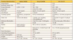
At the heart of any automated inspection system are the cameras. The main specifications of three popular monochrome cameras are listed in Table 1. Comparing the table entries will highlight characteristics of the different camera technologies.
Click on the image below for a larger view.
Mechanics
The Basler A402k, much larger and heavier than the other units in Table 1, is a digital CMOS area scan camera with 2,350 � 1,720 pixels each 7 � 7 �m in size. The overall rectangular sensor matrix measures at least 16.5 � 12 mm, which corresponds to a 20.4-mm diagonal.
In comparison, the JAI CV-A11 and the Sony XCHR58 are charge-coupled device (CCD)-based analog cameras. Neither directly lists the pixel size, but it can be determined from the nominal target size, 1/3″ for JAI and 1/2″ for Sony.
These values are not actual camera dimensions but instead refer to the equivalent diameter of old TV-style vidicon tubes. The new cameras follow the original TV 3:4 aspect ratio, but size designation is for reference only.
The most popular sizes are 1/2″ and 2/3″, which is the reason that JAI separately states its camera�s new compact 1/3″ size. For 1/3″, 1/2″, and 2/3″ cameras, the actual target areas measure 2.4 � 3.2 mm, 4.8 � 6.4 mm, and 6.6 � 8.8 mm with diagonals of 4.0, 8.0, and 11.0 mm, respectively.
Sony and JAI use the terms SVGA and VGA to describe camera target format. In fact, the video graphics array (VGA) and super VGA (SVGA) specifications do define display format, but they cover much more than that, including the number of colors that can be presented. In this case, the standards are only being referenced to indicate compliance with aspect ratio and pixel count. Sony provides 782 � 582 pixels vs. the 800 � 600 SVGA standard, and JAI has 659 � 494 pixels vs. the 640 � 480 VGA standard graphics mode.
Computation of the pixel size from these dimensions gives an 8.2-�m square pixel for the Sony camera, 4.9-�m for JAI, and 7.0-�m for Basler. Square pixels simplify camera-based measuring-system design because a certain number of pixels translates into the same dimension in both horizontal and vertical directions. However, the absolute size of the pixel also is important because it directly affects the amount of noise associated with the video signal and the signal�s dynamic range.
Targets
CCD-based cameras are available in two basic styles: line scan and area scan. Line scan sensors image a single line of the object and, to cover the entire area, require mechanical motion of the object or camera in a direction perpendicular to the line of CCD elements. Resolution and object size can be large with a line scan camera, but relative motion between the camera and object adds cost and complexity unless, for example, the object already is moving as in an automated handling operation. Area scan CCDs have an X-Y matrix of elements, the size of the matrix defining the resolution.
CCDs convert photons to electrons and trap the resulting charge in potential wells. The number of electrons trapped in a well corresponds to the intensity of the light reflected from a small part of the object being imaged. All CCDs are not created equal, and well capacity is one parameter that distinguishes among them.
If some parts of an object reflect a great deal more light than other parts, blooming may result in the image. This is caused by charge overflowing from a low-capacity well into adjacent wells. If a large dynamic range is needed, adequate well capacity must be provided. For example, a 1,000,000-electron capacity well approximately corresponds to a 10-b dynamic range.
For area scan CCDs, adjacent elements in a row are grouped into an analog shift register. After an image has been formed, all the rows simultaneously shift charge from element to element and into a column-shift register for readout. Between the relatively slow row-shift clocks, fast vertical column-shift clocks present each row�s charge packet to an output amplifier that converts it to a voltage level. The output of the amplifier is an analog video signal arranged in a column-by-column format.
Because charge will continue to accumulate during readout, a mechanical shutter is needed with a so-called full-frame CCD. The frame-transfer (FT) architecture provides a separate storage array that is not light sensitive into which the charges from the imaging array can be quickly transferred, avoiding the need for a shutter. Readout and conversion to a voltage signal are performed on charge packets in the storage array.
Interline (IL) CCDs alternate rows of storage and imaging CCD elements to reduce the large area and cost associated with FT devices. Having storage elements closely associated with imaging elements helps minimize image smearing that may occur in FT devices during the time required to transfer charge from one array to the other. IL CCDs generally have small pixels, which reduce sensitivity, although many devices use microlenses to enhance a pixel�s light-gathering capability.1
Cameras with IL CCD targets may achieve very fast shutter speeds of 10 �s or faster. Actually, there is no shutter at all, but the term electronic shutter refers to the capability within an IL device to precisely halt charge accumulation at a predetermined time. A short image integration time is necessary if moving objects must be inspected.
Large CCD arrays are possible, and these devices typically are subdivided into smaller sections functioning in parallel to maintain high-speed operation. For AOI applications, progressive scan cameras are used rather than alternate-field cameras similar to TV cameras. One frame of progressive scan video contains information from all the scan lines, which simplifies image analysis.
To avoid the expensive special processing required in CCD manufacturing, CMOS targets have been developed. Through a combination of process refinements and sophisticated on-chip noise-reduction circuitry, the improved performance of CMOS targets has allowed them to encroach upon established CCD markets. Generally, CMOS cameras provide direct digital outputs.
Lenses
One effect of a large or small target size is the type of lens mount a camera offers. Sony and JAI use a type C, but the Basler camera has a larger type F mount as used on Nikon SLR cameras. The effective flange distance, the distance from the focal plane to the lens-mounting plane, is 0.690″ (17.53 mm) for type C and 1.831″ (46.5 mm) for type F.
Lenses must match the lens mount used by a particular camera. Obviously, the lens must correctly attach to the camera, but in addition, the lens must have been designed to accommodate the mount�s effective flange distance. This distance becomes part of the lens� rear focal distance, the distance from the lens� primary plane to the focal plane.
As an example of partial compatibility, a type CS lens will attach to a camera with a type C mount, but it may not focus properly. Type CS and type C mounts have the same size thread, but the flange distance is only 12.526 mm on the type CS vs. 17.526 for the type C. The rear focal distance for a CS lens may not extend the additional 5 mm.
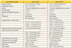
The specifications of two C-mount lenses are listed in Table 2 and show that the 16-mm focal length lens has a very wide angle of view (AOV) compared to that of the 75-mm lens. Other than the demands a large AOV places on lens distortion, a wide angle may contribute to spatial-sensitivity errors if an IL CCD sensor is being used in the camera. Light rays striking the microlenses at large oblique angles cause less response than rays closer to the axis.
Click on the image below for a larger view.
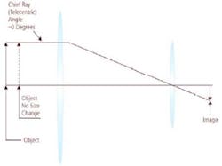
To eliminate AOV-related problems, some AOI systems use telecentric lenses (Figure 1). In these lenses, all rays entering the lens from the object are constrained to be parallel or nearly so. The lens behaves as though it had a very long focal length, and an object is imaged at a constant size regardless of its distance to the lens. Although perspective has been lost, a telecentric lens presents images ideal for measurement and analysis. A further refinement, the double telecentric lens, presents parallel light rays to the focal plane. Telecentric lenses must have a first element as large as the largest object to be imaged, so they tend to be both bulky and expensive.
Figure 2 shows the very simplified operation of a conventional lens. The focal length of the lens is approximately the distance from the lens to the focal plane when parallel light rays are entering the lens from the object side. Actual lenses are much more complex, using many elements and coatings to compensate for the errors a single lens produces.
The iris, an adjustable aperture within the lens, controls the amount of light that passes through the lens. If the iris has been closed down to a small opening, the extreme edges of the camera target will receive light rays at an angle of AOV/2 from the lens axis. This is the maximum angle because almost all the light imaged by the lens will pass through the lens center.
If, however, the maximum aperture is being used and the iris is wide open, light rays entering the lens at one edge will strike the opposite edge of the camera target. In the case of the 16-mm lens, this angle is shown in Figure 3.
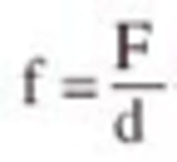
To compute the angle, start with the relationship
| where: | f = f/stop or relative aperture d = diameter of the effective aperture F = focal length of the lens |
For the 16-mm lens, the maximum relative aperture is listed as 1:1.4 or, equivalently, d = 16/1.4 = 11.4 mm. Light entering the upper edge of the iris when wide open will strike the lower edge of the target at an angle equal to tan-1 10.1/16 = 32.2�. With the iris stopped down to zero, the angle is equal to tan-1 4.4/16 = 15.375� or exactly one half of the AOV listed in Table 1.
Operating a lens at a high f/stop restricts light rays to the central area of the lens and improves depth of field although the image may be very dim. For a given lens, the depth of field is the total distance ahead and behind the object for which the focus is judged adequate.
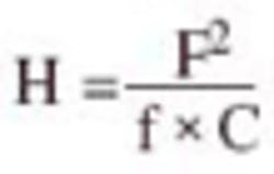
As an example of determining depth of field, first find the hyperfocal distance H for the 75-mm lens
| where: | C = diameter of circle of confusion H = hyperfocal distance, the distance beyond which everything will be in focus when the lens is focused at infinity |
Focus is subjective, and to quantify what is meant by focus, the concept of circles of confusion is used, corresponding to the out-of-focus circles formed by light rays from outside the depth-of-field range. A rule of thumb that yields acceptable focus for photography limits the diameter of the circles of confusion to 0.001 � F or 0.075 mm in this case.
The maximum relative aperture is 1:1.8, so the hyperfocal distance H = 75 � 75/(1.8 � 0.075) = 41.67 m. The depth of field relates to the hyperfocal distance by
where: D = distance focused upon
For this example, let D equal the minimum object distance of 800 mm. Then, depth of field = 41,670 � 800 � [(1/40,870) � (1/42,470)] = 30.7 mm or about 1-1/4″. In contrast, if an f/stop of perhaps 1:8 is used, the hyperfocal distance reduces to 9.376 m, and depth of field increases to 137.5 mm or >5″.
Another approach to depth of field considers the diffraction that lenses cause because the light rays being focused at a point are not in phase with each other. As a result, constructive and destructive interference occurs, forming a so-called Airy disk instead of an infinitely small focused point. The diameter of the Airy disk is given by
where: l = wavelength of the light
Because the wavelength of visible light is about 0.5 �m, the diameter of the Airy disk is approximately equal to the f/stop number of the lens. This means that increasing the aperture will reduce the image blurring caused by diffraction. In AOI applications, it is common to set DAiryAiry = 8.2 �m, corresponding to an f/stop number of about 1:8. If the allowed geometric defocusing (circles of confusion) also is set to 8.2 �m, the depth of field for the 75-mm lens is defined as equal to the size of one pixel. So, for the Sony camera, D
For this lens, the magnification is equal to the camera target width divided by the maximum object width at 800 mm or 6.4/68 = 0.094. The image is 9.4% the size of the object, and depth of field = 15.6 mm. If in the depth-of-field calculation based on the hyperfocal distance, the diameter of the circles of confusion had been set to 0.0082 mm (8.2 �m) rather than 0.075 mm, the resulting depth of field would have been 14.92 mm.
Summary
Although some aspects of cameras and lenses have been discussed, lighting, the size of the objects you are working with, and the speed with which inspection must be accomplished all are parts of real AOI applications. Because so many variables are involved, consulting AOI experts early in a project can save you considerable time and money.
You also may wish to contact AOI system manufacturers to guarantee a clear understanding of machine specifications. The capabilities of machines vary considerably so you may not be able to make direct comparisons among different brands.
For example, Vectron claims faster and more comprehensive analysis for the K2-AOI system because of its 4″ � 6″ large-format capability. A single 6,000,000-pixel, 24-b color image is quickly obtained compared to the operation of a line scan camera that involves physical motion. If the PCBs being inspected are smaller than 4″ � 6″, they do not have to be repositioned.
View Engineering has introduced a dual-magnification system to improve accuracy while maintaining flexibility. Two cameras with a 4:1 difference in magnification allow instantaneous electronic switching. A low magnification is used for part/feature alignment and a high magnification for accurate measurements.
In the Model SJ50 AOI System, Agilent Technologies has achieved both 23-�m resolution from a 2-Mpixel 1,200 � 1,600 camera and an inspection rate up to 3-1/4 in.2/s due to a high-speed motion system and two algorithmic engines for pattern matching.
The Cognex BGA II Multiple Field of View (MFOV) Inspection Tool allows you to divide larger device images into several fields of view using a standard resolution camera. The tool then forms a single composite image by combining the results of each individual inspection.
These specific products are just a small sample of the diverse range of available AOI systems and software. If you think you may need a machine vision system or already have one and want to better understand its operation, the material on the www.machinevisiononline.org website is recommended reading. All aspects of machine vision are covered by a series of articles that often includes the practical experience of a panel of experts.
Reference
1. Charge Coupled Device (CCD) Image Sensors CCD Primer, Eastman Kodak Company Image Sensor Solutions, MTD/PS-0218, Revision 1, 2001.
on Sony cameras
www.rsleads.com/407ee-185
on JAI cameras
www.rsleads.com/407ee-186
on camera targets
www.rsleads.com/407ee-187
on lenses
www.rsleads.com/407ee-188
July 2004

