Although Arbs eventually may become the ultimate RF generators, today many RF applications can be addressed using the latest instruments.
Arbitrary waveform generators (Arbs) are among the most pow-erful and flexible tools available to any test engineer. Their unique capability to generate any signal within the reach of their basic specifications makes them the instrument of choice when real-life signals are required.
The basic architecture of any Arb is very similar to an inverted version of a digital storage oscilloscope. The samples defining the waveform are stored in a waveform memory, this memory feeds a digital-to-analog converter (DAC) at a rate defined by its time base, and finally the signal is amplified, filtered, or otherwise processed to meet the application requirements.
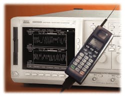
As in other test and measurement devices, wider, deeper, and faster explain the evolution of Arb performance. Sampling speeds higher than 4 GHz, converter resolutions up to 16 b, and waveform memory sizes close to 100 MS define the current state-of-the-art of the technology (Figure 1).
Figure 1. A High_Speed Arb
This increasing performance is helping engineers to better address traditional applications such as telecom, disk drive, electro-mechanical, and biomedical. At the same time, it opens new application areas such as RF/wireless testing.
Applying Arbs to RF
Arbs are not new to RF/wireless engineers. They have been used for years to generate complex waveforms, especially baseband or low-frequency IF signals. These signals can be used directly in many tests at both ends of the signal path.
Baseband signals, I and Q components, can be applied to modulators to create the required modulated carrier. Relatively low-frequency IF signals can be up-converted to the desired frequency.
Most of the complex modulation-capable generators on the market today use internal or external Arbs to create the signals required by modern wireless technologies such as Universal Mobile Telecommunications System (UMTS), wireless fidelity (Wi-Fi), and Bluetooth. There are many reasons that make Arbs a good fit:
-
There is no need for specialized hardware or embedded software to generate almost any kind of signal.
-
Traditionally, the capability to produce multiple carriers has been very limited due to the available bandwidth of modulators and up-converters. Arbs can generate any set of carriers from DC to the Nyquist frequency (half the sample rate). The same capability is useful for obtaining many signals at the same frequency, as is required in applications such as code division multiple access (CDMA) or interference simulation.
-
Virtually any distortion, linear and nonlinear, can be added to the signal. Although some RF tests require high-quality, low-distortion signals, many others use real-world impairments. Arbs can easily implement multipath, predistortion, or modulation impairments, even simultaneously.
-
Stand-alone Arbs are general-purpose tools that can be used in many applications besides RF/wireless test. Some high-end Arbs also incorporate parallel digital outputs that convert them into pattern generators. This capability is especially useful in testing DSP-based architectures such as software-defined radio (SDR).
The sampling speed, analog bandwidths, and record lengths make it possible to use today�s Arbs in another way in the RF arena: the direct digital synthesis (DDS) approach. DDS implies the direct generation of the signal at the required carrier frequency. This method takes the performance requirements to the limit but, in exchange, gives a great deal of flexibility.
Signals created in this way may contain multiple carriers ranging from DC to the Nyquist frequency. There is no practical limit to modulation bandwidth or symbol speed, and there is no need for expensive modulators or up-converters. But these capabilities do not come for free.
Understanding Performance
Arbs do have limitations. Some of them can be handled gracefully if they are known. Others may require further improvement of the technology.
One of the most common objections to using Arbs as RF generators is the available dynamic range. Some important tests in this application area, such as adjacent channel power ratio (ACPR), depend heavily on this specification.
There is a prejudice about resolution being the main contributor to the dynamic range or the lack of it. Even ideal DACs show the effects of quantization noise. Statistically speaking, this noise is a uniform distribution with a peak-to-peak value of 1 least significant bit (LSB). From the spectral standpoint, power distribution is flat or white from DC to half the sample rate (SR).
The most significant specification is the signal-to-noise ratio (SNR). For a sine wave running at full-scale amplitude, SNR can be calculated as:
SNRsine (dB) = 6N + 1.76
where: N = the resolution of the DAC expressed in bits
For any other signal, this expression should be corrected by the crest factor or peak to average power ratio (PAPR) and the fraction of the DAC output range used.
SNR (dB) = 6N + 1.76 – PAPRdB – 20 log10(FS/A)
where: FS = full-scale amplitude
A = peak-to-peak signal amplitude
But, is this the number an RF engineer tries to measure using a spectrum analyzer and real-world signals? No. What is important is the noise located at frequency bands occupied by the signals under study. In other words, the noise power density is important. Noise power density must be integrated over the signal bandwidth (SBW) to obtain the in-channel SNR.
|
SNR@sbw (dB) = |
6N + 1.76 – PAPRdB – 20 log10(FS/A) + 10 log10[SR/(2 x SBW)] |
To provide more meaning, let�s take a CDMAOne (IS95) downlink signal composed of the pilot, sync, and five user channels. The carrier frequency will be around 900 MHz, the chip rate 1.2288 Mchip/s, and the noise bandwidth 1.23 MHz. PAPR for CDMA signals depends on the number of channels and the way they are arranged. For this example, a typical PAPR of 9 dB will be used.
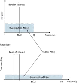
If the formula is applied to an ideal Arb with a sample rate of 4 GS/s and 8-b resolution, then SNR will be around 73 dB. Oversampling is responsible for this high value. Here oversampling is defined as the ratio between half the sample rate and the occupied bandwidth of the generated signal, not the maximum carrier frequency (Figure 2).
Figure 2. Oversampling Technique
If quantization noise is not a problem for many applications, what are the real limits for dynamic range? Well, dynamic range will be limited by other factors, especially those related to linearity.
Although linearity is difficult to express in a single spec, spurious-free dynamic range (SFDR) is the most descriptive for DACs. Typically, it measures the worst-case ratio between the fundamental frequency and any other spurious or nonlinear products such as intermodulations or harmonics.
Modern high-speed Arbs with sample rates as fast as 4 GS/s and high-linearity 8-b DACs show SFDR around 65 dB for 10-MHz carriers and about 45 dB for 400-MHz carriers. Linearity becomes more important than resolution in many applications, and the importance of spurious signals greatly depends on their location.
Record length is another important factor. Sampling rate, record length, and the available time window are interrelated. The higher the sampling rate, the shorter the time window will be for a given record length.
RF generation requires very high sample rates. Record length becomes an issue in applications where the statistical behavior is important. There is a requirement to accommodate a complete frame of symbols or implement any channel coding.
For example, a complete CDMAOne scrambling code sequence requires the transmission of 32,768 chips at 1.2288 Mchips/s. For 4-GS/s Arbs, this means more than 100 MS of waveform memory are needed. Generating the same signal at baseband needs less than half a million samples.
Wrap-around artifacts are another memory-related problem since the only way to create continuous signals in any Arb is by repeating the same segment or sequence of segments several times. These artifacts are produced when the beginning and the end of the signal are not consistent at all the required levels.
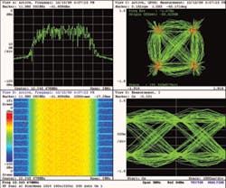
Depending on the application, these can include carrier, baseband filtering, differential modulation, channel coding, and all the implemented protocol layers. As a rule of thumb, the more levels that are implemented, the longer the record length that will be necessary to accommodate the symbols. A discontinuity at any of these levels will result in spectral leakage, the inability of the receiver to lock on the carrier or the modulation, and the impossibility of making accurate modulation quality measurements Figure 3.
Another problem related to a long waveform memory is the time required to compute the samples. Real-life multicarrier, digitally modulated signals involving many symbols require billions of complex calculations that may need a long compilation time. Number-crunching time is important when the application requires a high degree of interactivity or the signal contents depend on previous test results.
Analog bandwidth is yet another important specification. Using an Arb with enough sampling speed does not ensure that the required carrier frequency can be generated, at least at the expected amplitude level.
First of all, the sin (f)/f natural response of DACs, due to the zero order hold of typical DACs, will mean lower-than-expected amplitudes of the signals, especially if they are close to the Nyquist frequency where the attenuation due to this effect is 3.92 dB. The analog response of the Arb output signal-conditioning circuits is another factor. Nevertheless, some modern 4-GS/s Arbs provide 2-GHz analog bandwidth.
Improving the Signal
Most limiting factors can be improved by applying appropriate techniques. For example, dynamic range can be vastly improved by a number of strategies.
Sampling Rate
The higher the sampling rate, the lower the noise power density. Using Arbs with sample rates much higher than Nyquist is advantageous even when compared to lower speed, higher resolution instruments.
Oversampling improves quantization noise, but it does not affect linearity. Increasing the sample rate may require a longer waveform memory if the number of symbols must be preserved.
Linearization
Calibration of the DAC response may result in predistorted waveforms that will show a much better SFDR. A similar technique is commonly used in RF power-amplifier linearization. Calibrating high-speed, high-resolution Arbs is not an easy task, especially when dynamic linearity is an issue.
Noise Shaping
Sigma-delta techniques can remove quantization noise from bands of interest. This approach is especially powerful if used along with linearization since both require DAC calibration to obtain good results. Noise shaping is based on quantization noise feedback, and the best results are obtained when the real noise is used in the calculations. Knowing the real noise means knowing the actual response of the target DAC.
Signal Correlation
Minimizing the correlation among signals is especially important in situations where PAPR can reach high values such as multicarrier, CDMA, and orthogonal frequency division multiplexing (OFDM) signals. Additionally, correlated signals exhibit poor linearity. Allowing some clipping may help boost the available power, which increases the dynamic range, but it is a very crude method. Clipping in Arbs is extremely abrupt and, since there are no bandpass filters at the output, it means that spectral growth often will be too evident to be acceptable.
Wrap-around artifacts can be removed if signals are calculated properly at compilation time. Signals must contain an integer number of carrier cycles and symbols to solve receiver-lock problems. Special care must be taken to minimize the carrier or symbol frequency errors, especially when multiple carriers are involved.
Circular convolution also must be performed at the baseband level to avoid spectral growth and degradation of the modulation quality that result in a worse-than-expected error vector magnitude (EVM). Frequency shift keying (FSK)-like signals need an additional phase-matching process.
Calculation time is not always an issue. In some cases, the required signals are calculated once and stored in an internal nonvolatile memory in the target Arb. If this is not the case and waveforms must be calculated all the time, fast computers and efficient software packages are required.
The MCIQ software package from Tektronix is one example. It uses algorithms that do not require exact calculations at the baseband level while maintaining calculation noise beyond the requirements for ideal 16-b resolution Arbs.
Applying pre-emphasis may compensate frequency response roll-off, no matter whether it is induced by the DAC sin (f)/f response or the output circuit�s behavior. This is important in tests involving many carriers where high relative amplitude accuracy is required. Such equalization techniques will result in a reduced dynamic range.
The Future
As Arbs become more powerful with higher sampling rates, resolution, record length, and linearity, they will be even more useful in RF applications. The RF/wireless share of the Arb market is growing and, as a natural consequence, more and more RF-oriented features are being added, opening the door to specialized instruments. If sample rates were increased to more than 10 GS/s and analog bandwidth to 3 GHz or more and linearity improved, Arbs could rival the signal quality of specialized RF generators while outperforming them in flexibility and usability.
|
W-CDMA Compressed Mode Test And Sequencing Some high-end Arbs have the capability to run signal sequences at full speed. Sequencing minimizes the need for a large memory while providing a means to generate long-duration signals. This is accomplished by splitting the available waveform memory to accommodate several signal segments. These segments are sequenced at runtime by the contents of a sequencing list where each entry in the list incorporates the segment ID, the number of times to be repeated, and even a jump condition that can be controlled by external signals. Testing W-CDMA Compressed Mode is a good example of an application where sequencing is a mandatory feature. Compressed mode is used in handovers in 3G mobile telephony systems. It creates a momentary interruption in the transmission of any channel to allow the user equipment to make measurements of alternate radio links. Because many channels may be present at the same frequency, a realistic signal will show a random distribution in time of channels entering in compressed mode. To create such a signal, which may last for minutes, extremely long record lengths would be required. Sequencing gives a much better alternative because multiple short segments containing different versions of the radio link signal can be used instead. One of the segments will consist of one or more radio frames without any compression in it. Others would include any combination of compressed channels. The sequence memory will control the order the segments will be output so a realistic behavior can be accomplished. Signal segments for wireless applications must be calculated in such a way that wrap-around artifacts do not appear when jumping from one segment to the next. |
References
1. XYZ of Signal Sources, Tektronix Application Note 76W-16672-0, http://www.tek.com
2. Signals and Measurements for Wireless Communications Testing, Tektronix Application Note 76W-10555-1, http://www.tek.com
About the Author
Joan Mercad�, who joined Tektronix as an application engineer in 1987, has been involved in test systems design and instrumentation support for more than 20 years. He is the author of the MCIQ software package and holds a telecommunication engineering degree from the Polytechnic University of Catalonia, Barcelona, Spain. Tektronix, 14200 SW Karl Braun Dr., Beaverton, OR 97077, 800-835-9433, e-mail: [email protected]
on MCIQ Software www.rsleads.com/407ee-181
on W-CDMA compressed mode testing
www.rsleads.com/407ee-182
July 2004


