An industry expert discusses the factors you need to consider when purchasing or creating an EMC test software package.
For any of us who have put on a pair of black plastic headphones and plugged into the front of one of Dick Stoddart�s receivers, in those days, automation was a concept found in science-fiction novels. For those of you who do not have a clue what I am talking about, let me give you a little background.
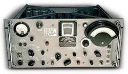
As electronics in the military and aerospace environments became more complex and elaborate, so did the sensitivity to electromagnetic fields�or in those days, radio frequency interference (RFI). We would dig out MIL-I-6181 (or in later years MIL-STD-461A) and our equipment to be tested and head to the lab where the NM-40A Radio Frequency Field Intensity Meter was plugged in and warming the room (Figure 1).
Figure 1. NM-40A Radio Frequency Field Intensity Meter
Measurements were made by slowly tuning the receiver over a frequency range, watching the needle for movement, and listening to the headphones for the type of signal. When the signal was quiet, it likely was a CW signal and usually narrowband. If it was noisy, there was a possibility of it being broadband. However, to determine if it really was broadband, you could tune two bandwidths above and below the peak of the signal. If the reading dropped 3 dB when moved two bandwidths above and below, we considered this a narrowband signal; otherwise, it was a broadband signal.
Another method was to measure the pulse repetition rate of the signal, and if it exceeded the bandwidth, it was narrowband. Are you with me so far?
Okay, we had one reading, which we corrected for antenna factors, cable losses, preamplifier gain, and, if it was a broadband signal, the broadband correction factor. Other known gains or losses had to be corrected as well. After all this, we had our first data point.
When I operated an EMC testing laboratory for my first employer, an aerospace company, the standard operating procedure was to schedule a 40-hour week to perform conducted emissions testing and evaluation. In the 1970s, the company acquired a used HP 141T Spectrum Analyzer and connected a chart recorder to it. This was great for doing broadband measurements; however, the slew rate on the chart recorder was so slow that narrowband measurements had to be performed by storing the signal on the screen and taking a picture with a Polaroid camera. Scans were performed in one-decade bands, and limit lines were drawn by hand.
By the 1980s, the IEEE 488 Instrument Control Bus, also known as the Hewlett-Packard Interface Bus (HPIB) or General-Purpose Interface Bus (GPIB), was standard on most equipment. Now we had the ability to control equipment from computers, download the data, correct the data for gains and losses, and plot the result.
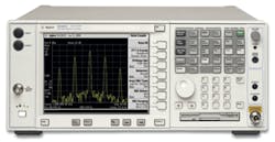
Figure 2. Agilent E4440A Spectrum Analyzer
Our Eaton Series VII Receiver System was controlled with an HP 9836 Computer using HP Basic. I could perform a broadband conducted emissions scan from 20 kHz to 50 MHz in about one minute.
Up to this point, I have only discussed military and aerospace emissions testing and not commercial testing. I also have not touched on other areas, such as susceptibility or immunity testing, in what we now call electromagnetic compatibility (EMC) testing. Each of these areas should be studied when purchasing or creating an EMC test control software package.
Emissions Testing
When obtaining an EMC control software package, first consider which tests you need to perform. Distinguishing between development work vs. final test and between radiated vs. conducted emissions will greatly simplify the EMC software selection process.
In development work, flexibility is key. It is important to be able to repeat a test several times, test over a limited frequency range, change sweep speeds, track signals, maximize a time-changing signal, measure the bandwidth of emissions, change the bandwidth of the analyzer, and determine harmonic frequencies.
For commercial work, the most common testing is radiated emissions. For military and aerospace work, it can be either radiated or conducted depending on the product you manufacture. Power supply manufacturers will be very interested in conducted emissions while control and display manufacturers often are more interested in radiated emissions.
In the commercial electronics world, this will include tests based on CISPR 22 and FCC Part 15, often performed in a shielded environment such as a screen room or shielded enclosure. FCC Class A and most CISPR testing require a 10-m distance from the antenna to the equipment under test.
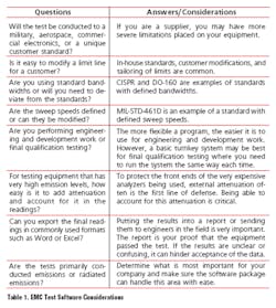
Most likely, the shielded enclosure will not be this large, and some type of allowance must be made for the change in test distance. Even if a basic 20-dB/decade modification is made to the data, this will yield results close enough for assurance when you take the product to an open area test site and measure at the proper distance (Table 1).
Susceptibility and Immunity Testing
The basic control software to perform conducted and radiated susceptibility or immunity testing must:
� Control a signal source, which then is amplified. The signal is sent to an antenna, current probe, coupling decoupling network (CDN), or other injection device.
� Obtain a feedback signal, such as provided by a directional coupler, that monitors how much power is being sent to the injection device. This forward power must be maintained so that the test level always is obtained but not exceeded by a certain amount; for example, power levels to produce the test level or up to 2 dB over the test level.
� Compare the feedback signal to a previously calibrated level and then adjust the signal source to maintain the test level inside this margin.
� Monitor induced currents or field strengths and then reduce the induced signal to maintain a safe test level.
� Generate or insert a test-frequency list. This may be based on an incremental increase in frequency, such as 1% higher than the last frequency, or a specific step size such as 1-kHz steps or 50-kHz steps. It may change during a scan if a company decides to test at step sizes smaller than required by SAE J1113 and test every CB radio frequency and do so at a higher level than the standard testing.
� Monitor support equipment to identify susceptibility to the test signal. In some cases, it may be advantageous to record this data into the test sheet. If a datalogger has GPIB control, can this be placed on the control bus and the data downloaded into the test computer for every frequency tested? Can the time be logged during the test to assure a proper soaking time at each frequency?
These capabilities should be available during a susceptibility or immunity test. The software needs to be flexible enough to obtain and record this information throughout the test.
Modulation of the test signal is very important. If a sine-wave amplitude modulation is used, then the equipment that monitors the forward power must make allowances for this modulation. For example, a spectrum analyzer monitoring forward power will record the top of the modulation envelope. However, this is not the proper amplitude to record and must be modified for the depth of modulation.
For medical devices, a very slow pulse modulation must be used during testing. Field probes and other equipment may not properly record the full value of the signal. Again, allowances must be made on how these modulations will be measured and errors avoided.
When performing the test, is it possible to test a limited frequency range? Is it possible to start at some frequency other than the test start frequency? Can items on the control bus be turned off and on easily? Once the data is obtained, can it be downloaded into a convenient format such as Word or Excel? Answer these questions when reviewing software and evaluate how important each of these functions will be.
Calibration
Although most critical equipment such as spectrum analyzers and power meters must be calibrated at a metrology laboratory, some items are easy to check yourself. Cable losses, pre-amplifier gains, current probe gains, and attenuators often are verified in-house.
The software must be able to perform A-to-B comparative sweeps, and then the difference can be used for a transducer file or gain/loss factors. These factors are used by the software during emissions or susceptibility/immunity testing. The program must be flexible because these factors can cover a wide variety of frequency ranges, amplitudes, and types of equipment.
Ease of Use and Flexibility
It is very common to change a limit line or other test parameters at odd times. I have lost count how often I have had a customer who has flown in from overseas to observe a test. These tests often are performed on Saturday or Sunday, usually after 8:00 p.m., and without fail, the customer will want to change something. It is not likely you will reach an applications engineer at the software manufacturer to help you make this change, so you will have to do it yourself.
In each software package I have used, I found a degree of complexity. Sometimes these areas can be learned over a few days; sometimes it takes longer. Be sure you understand how difficult it might be to change equipment or a test parameter before purchasing the software. If flexibility is important, this aspect will be vital.
Conclusion
Now we have a basis for how this software will need to operate. In Part 2 in the November issue of EE, we will look at software packages that are on the market today.
About the Author
Patrick G. Andr�, president of Andr� Consulting, has worked in the EMC field for 21 years and is NARTE certified as both an EMC and an ESD engineer. He received a degree in physics from Seattle University in 1982 and worked in the military and aerospace environment for 21 years and in commercial electronics for the last 10. Mr. Andr� has been a member of the IEEE EMC Society for 20 years, serving as chairman, vice chairman, and arrangements chairman of the Puget Sound Section, and is a sound design engineer for the Seattle Gilbert and Sullivan Society and Pro A/V. Andr� Consulting, 12812 NE 185th Ct., Bothell, WA 98011-3121, 206-406-8371, e-mail: [email protected]
October 2004


