Today�s aircraft designs are piloting the need for new testing methods.
With the changing ways aircraft are designed and built, namely the inclusion of increasing amounts of composite material and the drive to provide more power for systems, the way aircraft are tested to ensure survivability to lightning strikes also is changing.
Modern commercial airliners are much lighter in weight to increase performance. One example is the Boeing 787 Dreamliner, which will propel 250 to 300 passengers over greater distances than previously possible.
To accomplish this goal, Boeing is using 50% composite material and a first in the aviation industry: all-electric systems for undercarriage, flaps, and flight systems. But by doing this, the electrical load just shot through the roof. As a result, each of the two engines is fitted with a 0.5-MW generator.
Not wishing to leave this potentially lucrative market to Boeing, Airbus announced the A350 with the same objectives as the 787. Airbus also has developed the much larger, double-deck A380 that will carry approximately 550 passengers over long distances. The key to these projects is new technology, and this, in turn, is driving the need for new testing methods.
Before an aircraft system integrator will include any equipment, basic requirements must be established that determine the equipment immunity should an aircraft be struck by lightning. For several years, the lightning environment for electrical and electronic systems installed on commercial aircraft has been certified according to SAE Aerospace Recommended Practice (ARP) 5413.1 This document provides guidance for regulating the dangers of lightning and is enhanced and adapted by additional requirements such as the Federal Aviation Administration (FAA) Advisory Circular (AC) 20-136 2, which specifies indirect lightning performance criteria.
The FAA circular refers to a document that provides a generic suitability for testing equipment and systems. This is the Radio Technical Commission for Aeronautics (R.T.C.A.) standard DO160 3, in particular section 22 that deals with the indirect effects of lightning. This document is widely accepted as an international standard, a position further enhanced by its close association and harmonization with the European equivalent document EUROCAE � ED14.4
DO160 revision E, in addition to providing a generic basis for testing, applies principally to aluminium aircraft structures and clearly needs some modification with consideration for the current composite technology. This aside, each aircraft manufacturer must ensure its designs can meet airworthiness requirements. Effectively, each newly designed aircraft could have a test standard written specifically to meet this goal.
In both cases, the single biggest change is brought about by the lack of a Faraday cage, which aluminium aircraft provide for shielding and as a convenient current path for lightning. Although each design has specific requirements, the foundation remains DO160 and its relevant waveforms.
DO160 section 22 sets out a widely accepted view of the test methods and immunity levels required for aircraft-mounted equipment called line replaceable units (LRU). These methods include recommendations for pin injection, cable bundle, and ground injection (GI) tests using waveforms designated 1 through 5.
The latest revision of DO160 clearly defines waveform 4 as a voltage test. However, section 22 indicates that the voltage can be applied either through GI or cable induction (CI) methods. These two requirements are divergent, and although the same impulse test generator can be used, coupling is very specific.
GI is accomplished simply by applying the impulse generator outputs between the ground plane and a cable shield. Provided the generator has sufficient energy, current can be pumped through the ground loop to apply interference effects. This works fine for metallic aircraft.
Composite aircraft, however, do not necessarily have the same grounding possibilities. Instead of a current being driven, the ground connection is removed and a potential applied between the cable and ground. Test equipment designed to produce hybrid waveforms, that is, defined into open- and short-circuit conditions, will perform either of these test methods.
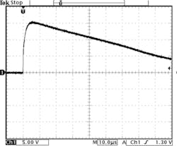
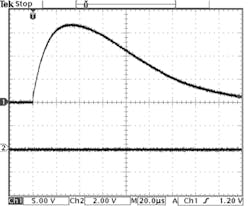
As a consequence of these generic DO160 waveform 4 discussions, aircraft manufacturers and system integrators are amending the DO160 requirements to match individual airframe and system needs. Waveforms 4 and 5A have been recommended for GI between an isolated EUT chassis ground and the test ground plane (Figure 1a and 1b). Under these conditions, with all shields connected, the likelihood is that for waveform 4 the current limit (IL) and waveform 5A the current test value (IT) will be reached before the voltage test value and limit, respectively.
Figure 1a. WF4 Level 5 in EUT Cable
Figure 1b. WF5A Level 5 in EUT Cable
Figure 1. Screen Shots of WF4 and WF5A
When a requested signal amplitude is applied, the test value is the level monitored in a test cable. The voltage or current limit is a monitored value that must not be exceeded because higher levels may result in EUT damage.
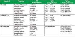
Airbus document ABD0100.1.2 5 for Avionic Full Duplex (AFDX) interfaces, a further development of the Ethernet protocol, and the Boeing D6-16050-5 revision B 6 introduce voltage tests applicable to the technology being implemented in the new generation of passenger aircraft (Table 1).
Depending on the impulse generator design, it may be possible to achieve the new test requirements using customised coupling devices. DO160 specifies testing of shielded cable bundles with shields connected at both ends but does allow for testing with shields disconnected, ensuring the test or limit voltage (VT) is achieved in the bundle core.
The increased interest in voltage tests due to changing technology is driving amendments in test requirements. A very specific requirement currently under review ensures that voltages measured in cable bundles are real impulses and not spikes introduced by instrument noise. It requires that voltage and current be simultaneously measured in the cable bundle.
Voltage should be measured using a loop on the coupling transformer and current measured with a coil on the cable harness. Using this configuration, it is relatively easy to determine whether a test voltage impulse is acceptable or not. Provided the voltage waveform passes through the zero crossing point after the current peak, the test is acceptable.
Test requirements for a new generation of engine management systems now are available. Full Authority Digital Engine Control (FADEC) units are an essential aircraft system connected to many sensors mounted in an exposed lightning zone, usually in the engine cowling. Because of this, particular attention has been paid to lightning test levels. Table 2 is a direct comparison of Waveforms 4 and 5A requirements between DO160 and FADEC applications in composite aircraft.
Conclusion
With the new industry-specific requirements being developed by prime aircraft designers, many manufacturers have been forced to seek alternative test methods. This is particularly true for current-based GI methods of testing because these types of generators may not reach the higher voltage threat levels.
An iron core transformer with the primary connected to the impulse generator and the EUT cable wound on the core as the secondary can provide very satisfactory results for voltage impulses. Figure 2 shows an example of such an amendment to an existing coupler. To achieve higher voltage levels in the EUT cable, a special additional coupling transformer must be designed so that the core will not saturate under impulse and EUT current loads.
References
1. ARP 5413: Certification of aircraft electrical/electronic systems for the indirect effects of lightning.
2. U.S. Department of Transportation Advisory Circular AC 20-136, May 1990.
3. RTCA/DO-160E: Environmental conditions and test procedures for airborne equipment, Section 22: Lightning Induced Transient Susceptibility, Dec. 9, 2004.
4. EUROCAE Aircraft Lightning Environment and related test waveforms, Document ED-84 Edition 2, May 18, 2001.
5. ABD0100.1.2: Equipment design, General requirements for suppliers.
6. D6-16050-5B: Electromagnetic Interference control requirements for composite airplanes.
Further Reading
1. Casanova, R. and Lutz, M., Induced Lightning Testing of Avionics – With Single Stroke, Multiple Strokeand Multiple Burst, EMC Partner AG, Laufen Switzerland.
2. Lutz, M. and Wright, N., Explanation and experiences with RTCA/DO160 Level 5 avionics testing, EMC Partner AG, Laufen, Switzerland.
About the Authors
Nicholas Wright started his career at the Royal Signals and Radar Establishment, Malvern U.K., and then worked on military projects for Marconi and GEC Avionics. Moving into the field of EMC, he has held posts as product manager and regional sales manager, culminating in his current position as international sales manager for EMC Partner based in Switzerland.
Leo Makowski is the president of HV TECHNOLOGIES. Previously, he was a manager with Cisco Systems where he worked for five years and as general manager and vice president of the EMC division of Haefely-Trench. Mr. Makowski also has participated with numerous IEEE EMC Society and standards activities and currently is secretary to RTCA SC-135. HV TECHNOLOGIES, 8515 Rixlew Lane, Manassas, VA 20109, 703-365-2330, e-mail: [email protected]
June 2006


