Heat flow considerations play an important role in any strategy for burning in high-power devices.
The purpose of burn-in with test is to significantly increase the reliability of high-power devices by detecting and eliminating parts that fail early in service. Devices are stimulated by various inputs, including pulsed inputs or built-in self-test (BIST) techniques. Device temperatures typically are held at set points from 100�C to150�C.
The maximum power levels that can be tested are determined by the thermal resistance of the device to its heat sink and of the heat sink to air and the power density of the part. Dynamic burn-in with test also may be used to determine the life span of a device or to weed out devices that fail under marginal conditions. This allows device manufacturers to significantly increase part reliability.
It is especially important to know the nominal power dissipation and the variation in power dissipation among all devices. Thermal resistance can vary by as much as 40% depending on the thermal interface between the die and heat sink, the surface area of the device, the number of pins, the pressure applied to the interface between the heat sink and die, and the heat sink surface finish. As device power levels increase, even small decreases in thermal resistance between the device and the cooling medium have a great effect.
If these factors are not compensated for, one device can become so hot it may be damaged while another device may not be adequately stressed. To stress all devices evenly, the temperature needs to be kept as close as possible to the test specifications.
Device Specifications
For device power of approximately 35 W or less, temperature can be controlled using individual heaters inserted into the heat sink and blowing cooling air over the test sockets. Heat can be added with individual heaters that pulse on and off as needed.
When the power goes above 35 W, another approach controls airflow onto the devices through air control valves. A heater is inserted into the heat sink to raise the temperature of the device by turning the heater on and off when needed. Cooling air is directed onto the devices through valves.
Thermal Resistance
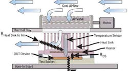
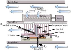
There are three main thermal resistances to consider when dealing with air-cooled sockets. RSA is the thermal resistance (convective) between the heat sink and the oven air. RDS is the thermal resistance (conductive) between the DUT and heat sink. RDA is the thermal resistance between the DUT and air.
RT is the total thermal resistance. RC is a combined thermal resistance for all heat flow paths not through the heat sink (Figure 1).
Figure 1. Thermal Resistance Factors
The equation to determine the total thermal resistance of a device with a heat sink is:
As device power levels rise, it is increasingly important to control and reduce the thermal resistance between the device and the cooling medium.
The minimum device temperature achievable can be determined as follows:
From this, you can derive the equation commonly used to calculate thermal resistance:
where RT is calculated using Equation 1.
So if a 100-W part is used in a system with a desired temperature set point of 100�C with a 30�C oven temperature, the resulting thermal resistance must be 0.7�C/W or less. Techniques to lower the thermal resistance include applying pressure to the interface between the heat sink and the device, maximizing the flow of air from the heat sink to the device, and reducing the temperature of the air.
DUT-to-Heat Sink
RDS is thermal resistance typically in the range of 0.3 to 1.5 �C/W. This parameter is a function of the following items:
� Flatness of Device and Heat Sink at the Interface Between Them�Air, which is not a good thermal conductor, will be present at any point where the materials do not touch.
� Treatment of the Interface�Thermal interface materials (TIMs) are available, which although sometimes messy and hard to remove, greatly reduce the requirement for flatness.
� Contact Area�The larger the contact area, the lower the thermal resistance. In general, this is not a linear relationship. As the contact area increases, the additional resistance benefit will decline. The contact area is largely determined by the geometry of your device.
� Contact Force�The higher the force, the lower the thermal resistance. This also is generally not a linear relationship. Sockets with heat sinks pressing directly on a bare die generally are limited to the range of 5 to 10 lb to avoid damage to the die. Heat sinks pressing on a heat spreader can apply the full force required to compress the contact pins; for example, 28 grams/pin � 1,200 pins = 33.600 kg = 74 lb.
Heat Sink-to-Air
RSA thermal resistance typically ranges from 0.3 to 3.0�C/W. This parameter is a function of the following items:
� Fin Configuration�Increasing the number of fins and thickness without impeding the airflow increases heat dissipation capability, which lowers thermal resistance.
� Airflow�An air-cooled design makes very efficient use of its available airflow. A high-velocity jet of air at a relatively low flow rate forced through the center of the heat sink does two things.
First, as incoming air enters the heat sink it passes over the warmest part of the heat sink. This provides the highest possible temperature differential between the air and heat sink surface.
Second, because of the high velocity, air can be forced through relatively small spaces between the heat sink fins. This allows for the design of a very efficient and compact heat sink as more volume can be devoted to the fins rather than the space between the fins.
� Heat Sink Material�A copper heat sink will more efficiently conduct heat from its base to the fins and the air. However, it also will be much heavier and more expensive than an equivalent aluminum heat sink. For most air-cooled systems, aluminum is the best heat sink material choice.
Thermal Resistance for all Other Paths Combined
RC thermal resistance is primarily from the socket through the burn-in board (BIB) to air. This generally ranges from 2�C/W to 7�C/W and primarily is a function of the number and size of socket contact pins.
As an example, a through hole socket with greater than 1,500 pins will conduct a lot of heat into the BIB and have a lower RC, closer to 2�C/W. A surface-mount socket with fewer than 500 pins will conduct less heat into the BIB and have a higher RC, closer to 7�C/W. The socket backer plate also can have a small effect on the thermal resistance.
Temperature Measurement
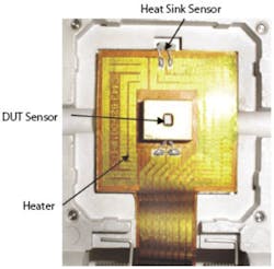
The temperature of each device must be accurately measured since it is an input to the control system. In most cases, it is advantageous to insert a temperature sensor in the heat sink so that it makes contact with the device. Three sensor types typically are used: resistive temperature devices (RTD), thermocouples, and internal diodes. Figure 2 shows typical sensor locations for a device and heat sink.
Figure 2. Typical Sensor Locations
As their name indicates, RTDs rely on the resistance change in a metal with the resistance rising linearly with temperature. This type of sensor uses materials that have a variable resistance depending on the temperature of the surrounding area.
While the most expensive sensors, they are accurate and easy to read. However, they also are generally larger than a thermocouple, which increases the socket size and decreases the contact area and the device-to-heat sink capability to lower thermal resistance.
Thermocouples consist essentially of two strips or wires made of different metals and joined at one end. Changes in the temperature at that juncture induce a change in electromotive force (EMF) between the metals. As the temperature goes up, this output EMF of the thermocouple rises. Thermocouples are common and inexpensive. They are easy to mount, but to provide accurate readings, junction compensation is required at an extra expense.
Internal diodes are embedded in the device to determine the temperature directly by measuring the voltage drop across the diode for two or three different applied currents. It is inexpensive and precise. However, a poor quality socket connection can prevent the measurement.
Using an internal diode requires two pins on the socket, which may slightly impact the size of the device. Also, most internal diodes can only withstand temperatures of up to 150�C.
Sockets
Selection of good sockets is a must. As the contact spacing has decreased, designing and manufacturing good sockets have become very difficult. Many of the problems encountered involve intermittent connections at the burn-in socket.
It is very important to provide adequate bypass capacitors at each burn-in socket to minimize power supply noise and ripple.
While socket size has increased, so too has the complexity of PCBs. BIBs can have 10 to 20 layers of copper for routing power, ground, and signal traces.
To withstand high temperatures, most BIBs are fabricated from polyimide material. With such close spacing of signal traces and pins, there are many opportunities for BIB failures in the form of shorts and opens. This makes testing for opens and shorts critical. In addition, to maintain signal integrity, it is necessary to properly route and terminate the signal lines.
Power Considerations
The power supplies used should have programmable outputs with less than 40-mV peak-to-peak ripple and noise as well as programmable over-voltage, under-voltage, and over-current protection.
Software
Software is required to support engineering and production environments. It must easily specify voltage, temperature, and test sequences; provide test-in-progress monitoring, especially for device temperature at each socket; and control device temperature at each test step. A good software package will allow you to customize the test to specifications and run reports on each test.
Conclusion
High-power burn-in requires the consideration of several factors when choosing a solution including device power, size and design of the heat sink and socket, method of temperature measurement, and power requirements. All of these impact the thermal resistance of the device, which ultimately impacts the capability to stress devices at high temperatures.
You must navigate a fine line that allows the device to be adequately stressed without damaging the part. The burn-in strategy used must be cost efficient but reliable. The savings will be evident to the manufacturer as well as to the end consumer.
About the Authors
Harold E. Hamilton is founder and president of Micro Control. He has a B.S.E.E. from the University of Nebraska and an M.S.E.E. from the University of Minnesota. e-mail: [email protected]
Jeffrey C. Urbanek is a technical writer at Micro Control. He earned a B.A. in English and an M.A. in journalism from the University of Wisconsin-Madison. e-mail: [email protected]
Micro Control, 7956 Main St. SE, Minneapolis, MN 55432, 763-786-8750.
July 2006


