Building a successful microwave test system requires the use of many different components to control signal flow, signal level, and signal integrity. The design engineer must consider the impact of signal-path components on system requirements such as VSWR, insertion loss, and power handling capability. Choosing the right components helps ensure that system design parameters are met.
Attenuators
Attenuators are used in a wide variety of applications to satisfy almost any requirement where a reduction in power is needed. Attenuators can be either fixed or variable and can:
� Balance out transmission lines that otherwise would have unequal signal levels.
� Reduce signal levels to spectrum analyzers, power meters, and network analyzers.
� Improve the VSWR of a poorly matched load or source.
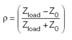
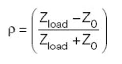
When a load is perfectly matched to a source, the maximum power available from that source is transferred to the load. Under these ideal conditions, there are no reflections, the reflection coefficient is zero, and the VSWR is 1.0:1. The reflection coefficient can be expressed in terms of the load impedance and the characteristic impedance as
VSWR can be expressed in terms of reflection coefficient
Return loss often is used to express the amount of signal reflection in decibels. It can be calculated from VSWR
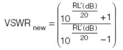
The introduction of a fixed pad will reduce the amount of signal reflection and, as a result, improve VSWR. Because the reflected signal travels twice through the signal chain, the return loss will be reduced by twice the attenuator value
The improved VSWR is calculated as
As a rule of thumb, a test system with a return loss greater than 20 dB (VSWR <1.20:1) can make very accurate RF measurements.
There are some drawbacks when inserting attenuators into test systems. For example, if a 10-dB attenuator is inserted in the front of a spectrum analyzer, the spectrum analyzer noise figure will increase by 10 dB and the measurement dynamic range will decrease by 10 dB.
It also is possible to degrade VSWR by introducing the attenuator. If the attenuator VSWR is worse than the source or load that you are trying to improve, the effective VSWR will be degraded. It is important to use high-quality attenuators with low VSWR.
RF Switches
RF switches are vital parts of automated test systems. The purpose of an RF/microwave switch is to route signals between measurement instruments and the DUT. With the use of an RF switch, an instrument can measure or source multiple DUTs without the need to change cabling for each one. Multiple tests with different instruments can be run on the same DUT, or multiple instruments can test multiple DUTs.
When switch speed is not important, electromechanical switches typically are used. Compared to solid-state switches, electromechanical switches have wider bandwidth, lower insertion loss, and better isolation.
Reliability is a major concern when using electromechanical switches. Typical electromechanical switches have a lifetime of at least one million closures. Premium electromechanical switches guarantee five million closures.
Electromechanical switches with indicators allow an automated test system to monitor and count switch closures. An automated test system should keep a count of switch closures and alert the user when a switch is nearing the end of its operational life.
When fast switching speed is required, a solid-state switch is necessary. Switching speed is dependent on the power rating of the switch. Generally, a solid-state pin diode switches between on and off states on the order of 50 ns to a few microseconds, making them much faster than electromechanical switches that take from 40 ms to 100 ms to switch.
Solid-state switches are designed using pin diodes. Essentially, a pin diode is a voltage-variable resistor. With the diode forward biased, it is in the conduction state, and the switch turns on. With the diode reverse biased, the switch is in the isolation state.
Isolation of the switch is limited by the diode capacitance. Increasing the size of the pin diode reduces the capacitance and increases the isolation. Unfortunately, larger diodes have higher insertion loss and decreased switching speed. Switch selection is based on the best trade-off among isolation, insertion loss, and switching speed.
Directional Couplers
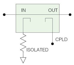
A directional coupler has the capability to separate and sample signal components based on the direction of signal flow. The directional coupler splits a signal into two unequal components with the coupled output attenuated by the coupling factor (Figure 1).
An ideal directional coupler only permits RF to flow in the direction for which it is designed. Directional couplers are not ideal and also allow a portion of the signal to flow in the reverse direction. The difference between the coupled port�s output with power flowing in the forward direction as compared to its output with power flowing in the reverse direction is referred to as directivity.
When specifying a directional coupler, the important parameters are frequency range, coupling value, insertion loss, VSWR, and directivity.
Insertion loss typically is specified as the ohmic loss of the coupler and does not include signal loss due to coupling. The true insertion loss is the combination of the ohmic loss and the loss due to RF coupling. The true insertion loss can be calculated as
where: CPL = coupling value in dB
Power Splitters and Dividers
Power splitters and dividers commonly perform many functions in a test system. Some of their uses include combining multiple signal sources, splitting a signal source to different DUT inputs, and monitoring the RF level.
Resistive Power Splitter/Divider
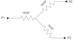
Frequently, the need arises for a very broadband power splitter or divider for combining signals. The resistive power splitter/divider can work over many octaves. In fact, there are commercially available resistive dividers that cover DC to 40 GHz. In addition to their broad frequency range, they are very compact.
The basic structure is shown in Figure 2.The resistive power splitter suffers some serious drawbacks. In the resistive divider, half of the input power is dissipated. Another disadvantage is the lack of isolation between output ports. Any mismatch on one output will be reflected to the other output.
Lossless Power Splitter/Divider
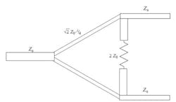
An example of a lossless power splitter/divider is the Wilkinson power splitter. The design uses two quarter-wave transformers to match the split ports to the common port at the center frequency. A one-section Wilkinson power divider is shown in Figure 3.
The Wilkinson splitter can provide 20-dB isolation narrowband and 15-dB isolation broadband. A one-section Wilkinson typically achieves good performance over one octave, but additional sections can be added to achieve wider bandwidths.
Circulators and Isolators
Isolators and circulators ensure that good impedance matching is obtainable, prevent undesirable VSWR interactions by absorbing reflections, and provide RF isolation. A circulator is a three-port device that allows RF energy to travel in only one direction. An isolator is a circulator with the third port terminated. Any RF energy traveling in the opposite direction will be absorbed in the third-port termination.
Isolation is a function of the intrinsic VSWR of the circulator and the VSWR of the termination. Most isolators are specified at 20 dB but values of 26 dB can be obtained for narrowband applications.
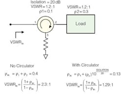
An isolator can improve the VSWR of a test system by absorbing the reflections of a high VSWR load. As components are added to a system, the reflection coefficients will multiply, degrading the overall VSWR. An example of the VSWR improvement by a circulator is shown in Figure 4.
Conclusion
Understanding how different components affect measurement path losses, VSWR, and measurement errors is essential in building an accurate microwave measurement system. By knowing the operation of the common microwave components, the engineer can trade off measurement accuracy, VSWR, and RF path losses to obtain the best solution for the measurement application.
About the Author
Ed Crean is senior RF engineer at Symtx and has 22 years of experience in RF design, manufacturing, and management. Before joining Symtx, he specialized in high-power RF amplifier design and development at Nokia and Andrew Corp. Mr. Crean holds a B.S.E.E. from the University of Buffalo and an M.S.S.E. from Texas Tech University. Symtx, Subsidiary of AAI, 4401 Freidrich Lane, Austin, TX 78744, 512-328-7799, e-mail: [email protected]
March 2007
