As the lights dim, a hush falls over the hundreds of delegates anxiously awaiting this year’s announcement. And the product elected to the Test Instrument Hall of Fame is (opening the envelope) the Pulse Generator! (Applause and cheering, hugs and congratulations, a few tears from the losers.
The pulse generator won a majority of the delegate votes because it has helped the development of so many successful products. For example, a pulse generator simulated the encoded pulse trains at the heart of an infrared TV remote controller. A pulse generator provided the pulse width modulated (PWM) outputs to a prototype motor drive�s power stages. And, how would the solenoids in electrically controlled door locks be life-tested without a pulse generator?
These and many other apparently straightforward applications are solved every day by pulse generators. As you may expect, there are many types of generators to suit different needs. Years ago, before such a wide range of functionality was available, engineers mocked up small circuits with counters and decoders to generate the specific pulse patterns they needed. Of course, that circuitry usually was driven by a simple pulse generator serving as a clock signal.
Since then, pulse generators have developed in several dimensions. The basic generator produces one or two pulses with variable amplitude, width, and repetition rate. Pulse-pattern generators add programmability in the time axis. Within limits, you can define the widths, positions, and the repetition rate of a succession of pulses.
Arbitrary waveform generators (Arbs) are programmable in both amplitude and time and can produce virtually any waveform with any amplitude and timing. Of course, you can use an Arb as a pulse-pattern generator simply by restricting the shape and height of the pulses.
Similarly, a function generator is a source of sine, triangle, and square waves. If duty cycle and repetition rate controls are available, the square-wave output can be altered in width and frequency to provide the required pulse signal.
Basic Pulse Generators
The Geotest Model GP1612H Programmable Pulse Generator is representative of basic pulse generators and a direct replacement for the obsolete HP8112A Pulse Generator. In many cases, the cost of test-procedure upgrades can be avoided by substituting exact replacement instruments when the original no longer can be obtained and cannot be repaired or maintained economically.
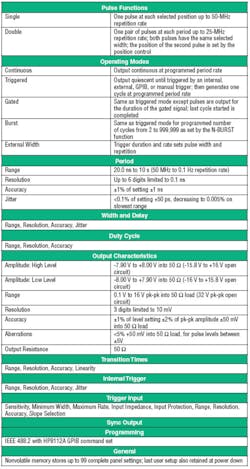
Table 1 lists the major specifications of the GP1612H. More sophisticated products such as pulse-pattern generators or enhanced-performance units with high power or voltage outputs are based on fundamental pulse generator capabilities.
Table 1. Abbreviated GP1612H SpecificationsCourtesy of Geotest-Marvin Test Systems
To keep Table 1 a manageable size, many details have been listed by type rather than value. For example, both the pulse width and its delay from the trigger have a range of values, a smallest resolution applying to those values, an accuracy, and an amount of jitter or uncertainty. Many improvements have been made in newer instruments, but these fundamental parameters still apply.
Today�s relatively straightforward pulse generators typically are low cost and have similar or less flexibility than the HP8112A. For example, the single-channel Protek Model B1990 Pulse Generator provides variable pulse width and delay, a 10-MHz repetition rate, and a 5-V maximum output into 50 ?. The rise time is specified to be a fixed 10 ns. Nevertheless, there are many uses for these basic capabilities.
C&H Technologies makes the MA209 Programmable Pulse Generator in the M-Module format for use with VXI, VME, PCI, and cPCI M-Module carrier boards. This is a single-channel generator with similar capabilities to the HP8112A, but the repetition rate is specified as 0.093 Hz to 100 MHz, output levels are from -1.5-V to 6.5-V open circuit, and pulse width ranges from 5 ns to greater than 10 s. A reference oscillator input supports phase-locking the generator to a 10-MHz external clock.
A number of system-oriented features distinguish this generator from a general-purpose benchtop instrument. They include programmable input thresholds on the gate, trigger, and reference clock signals and a choice of front-panel or M-Module backplane signal source/destination.
C&H President Fred Harrison said, �To date, most of our pulse generators have been traditional with a few of our specialized designs being higher voltage or sequencing on multiple outputs. Typical applications have included the primary synchronization clock for a semiconductor ATE, as legacy replacements used in combination with signal conditioning M-Modules, and as primary clocks for UUTs on a number of test sets.�
Pulse Pattern Generators
Several test and measurement instrument manufacturers have developed new pulse generators with digital communications in mind. This application space includes computer I/O buses as well as wireless formats such as WiFi and, most recently, WiMAX. These instruments feature pulse-pattern capabilities and generally run at much higher repetition rates.
For example, the Agilent 81100 Series Pulse Pattern Generators include models with a 660-MHz repetition rate. At this fast speed, pulse transition times are fixed or selectable between two values. There also are models such as the 81101A much closer in performance to the HP8112A. This is a list of the changes made to the basic specifications:
� Minimum repetition rate reduced to 1 mHz from 100 mHz.
� Maximum width and delay ranges increased from 9.8 s to 999.5 s.
� Jitter reduced from 0.1% of setting + 50 ps to 0.01% + 15 ps.
� Output amplitude extended to 20 V open circuit from 16 V and levels set as a combination of offset and amplitude.
� Maximum transition time extended from 100 ms to 200 ms.
� Source impedance switchable between 50 ? and 1 k?.
Equally important, the newer platform supports features such as a graphical display, autoset, and preset TTL/ECL levels. On higher-performance models in the family, double pulse and pattern mode capabilities have been added. Pattern mode provides a pseudorandom bit sequence (PRBS) and in some models also can be programmed to output pulses as required within the limitation of 16-k possible positions. The pulse output format is selected from return to zero (RZ), non-return to zero (NRZ), or delayed NRZ (DNRZ).
Pattern mode reflects the move to serial data communications that has been in progress for several years. It also relates to the prevalence of digital circuitry instead of analog and the associated need for more complex digital signal generation.
Series 3400 Pulse/Pattern Generators from Keithley Instruments also fall into this category. The Model 3401 is a single-channel instrument while the 3402 adds a second channel. The repetition rate and basic mode of operation are common to both outputs, but width, pattern, transition time, and delay can be set independently.
These instruments feature wide operating ranges such as the 1-mHz to 165-MHz repetition rate and 3-ns to nearly 1,000-s pulse width. Patterns must fit within the 16-k memory, and if separate patterns are programmed for each channel, they must be the same length. NRZ and RZ formats apply to either the built-in PRBS pattern or user-programmed patterns. The generator can be phase locked to a 10-MHz external clock.
Commenting on the importance of new technologies in his company�s products, TEGAM�s President Adam Fleder said, �The high level of integration offered by an FPGA-based design enabled us to combine a function generator using direct digital synthesis, an Arb, and a pulse generator into one instrument. The 2700A Hybrid Series Function/Arbitrary Waveform Generators also include 4 MB of waveform memory that permits simulation of nonperiodic waveforms and pulses that otherwise is not possible.�
The user can control the frequency, amplitude, offset, phase, duty cycle, and rise/fall times of the standard sine, square, triangle, and pulse waveforms. Standard pulses have repetition rates from 0.5 mHz to 25 MHz, or using the generator�s arbitrary waveform capabilities, rise/fall times can be as low as 6 ns with a maximum 62.5-MHz repetition rate.
Fast Pulse Generators
Agilent�s Models 81130A/32A provide up to a 660-MHz repetition rate with typical transition times of 500 ps or as low as 200 ps for ECL levels. That�s fast, but the company classifies these models as precision pulse generators. Two-channel versions operate in a differential mode. However, the Models 81133A, 81141A, and 81142A are the high-speed family members with repetition rates up to 13 GHz.
Beate Hoehne, product manager, explained the positioning of these instruments, �The 81133A/81134A are 3.35-GHz pulse pattern generators targeted at cross-over point adjustment [duty-cycle distortion] and jitter insertion requirements for PCI Express or Serial ATA standards testing applications. The 81141A/42A provide the extremely short pulses and fast transition times needed in physical-layer stress tests. In addition, they are used by scientists conducting fundamental lab research.�
The 81141A/42A have fixed 10% to 90% rise and fall times less than 25 ps, output amplitude adjustable from 0.1 to 1.8 V, and an output voltage window from -2.0 to +3.0 V. This is another way of describing the interaction between amplitude and offset.
Specifications include 9-ps peak-to-peak typical intrinsic data jitter and a DC to 1-GHz delay input modulation bandwidth. One type of test deliberately injects jitter to determine how well the clock/data receiver (CDR) rejects it. Some communications standards specify a 500-MHz jitter bandwidth, so the generator must have an even higher bandwidth. Another aspect involves bit error rate testing for which very long bit sequences are needed. The 81141A/42A support patterns up to 16-Mb in length.
As pulse speed increases, most generators offer fewer control selections. For example, the Picosecond Pulse Labs Model 4005 5-ps Calibration Source is a relatively low repetition rate generator with a range from 0.1 Hz to 1 MHz. However, the pulse fall time is only 5 ps. For edges this fast, measurements are not straightforward. No longer can you ignore the rise time of the measuring instrument.
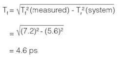
According to the datasheet, �The 4005 unit was measured with a 70-GHz scope�contributors to the system rise time include the scope (4.85 ps) and the averaged jitter (2.7 ps) for a total system rise time of 5.6 ps. The measured fall time was 7.2 ps.�
The actual pulse fall time is calculated from:
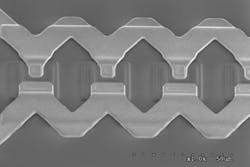
Pulses this fast can�t easily be generated with conventional circuitry. Picosecond Pulse Labs has developed GaAs nonlinear transmission lines (NLTL) for this purpose. Figure 1 is a SEM image showing a few of the many varactors arranged along the length of the line. NLTLs provide a different amount of delay to each voltage level in a signal. Low voltages are delayed more because the capacitance of the shunt varactors is higher at low voltages.
Figure 1. Scanning Electron Microscope Image of Nonlinear Transmission LineCourtesy of Picosecond Pulse Labs
Because higher voltages are not delayed as much, the parts of the pulse edge following a rising transition tend to catch up with the more slowly moving lower amplitude parts. This process sharpens the pulse rise time. To achieve the best results with this technology, separate pulse heads are used, each with a fixed output level.
In addition to instrument calibration, very fast edge generators are used in time-domain reflectometry (TDR). The faster the edge of the TDR pulse, the higher the frequencies that can be discerned for time-domain network analysis applications.
LeCroy has worked with Picosecond Pulse Labs to incorporate the NLTL technology into oscilloscopes. Dr. Mike Lauterbach, LeCroy�s director-product management, said, �We were the first company to use NLTL in the front-end sampling head of a very wideband oscilloscope, the 100-GHz WaveExpert�. The same NLTL technology is used to make fast edges, typically 30-ps rise/fall times for the high-speed PPG-E135 Pulse Generator.�
The PPG-E135 is intended for use with the WaveExpert scope. It is programmed via the scope menu system and plugs into one of the four module slots. An internal clock drives PRBS sequences up to 231-1 in length at rates from 50 MHz to 11.5 GHz. An external clock input operates to 12.5 GHz and allows synchronization to an external system. One of the benefits of NLTL technology in this application is its very low jitter specified to be <1-ps rms.
Tektronix describes the DTG5000 Series of data timing generators as �combining the power of a data generator with the capabilities of a pulse generator.� Data generators emphasize the quantity of outputs and their timing characteristics such as jitter. The Tektronix DTG5000 Series has a number of built-in patterns and provides jitter-generation capabilities for as many as 100 parallel channels.
Serial data standards require that a clock/data receiver operate correctly in the presence of a specified amount of jitter. Generating both the right amount as well as the correct composition of jitter is needed not only in serial data systems, but also in more general-purpose DAC, memory, and ASIC testing.
In addition, the DTG5000 simulates the operation of a complex digital circuit. Bob Buxton, product line marketing manager, explained. �The DTG can be used early in the product development cycle to substitute for system components that are not yet available. For example, it might be programmed to send interrupts and data to a newly developed bus circuit when the processor that normally would provide the signals doesn�t yet exist.�
Heavy-Duty Pulses
A few instruments with both source and measure capabilities also have a pulse mode of operation. Keithley�s Series 2600 System SourceMeter products combine a precision power supply, a true current source, a DMM, an Arb, a voltage or current pulse generator with measurement, an electronic load, and a trigger controller. Similarly, the Yokogawa GS610 Source Measure Unit also provides voltage and current sources and measurement and has a pulse output mode that can be combined with sweep capabilities.
If your application involves driving a solenoid or motor for a short period of time, these instruments may be good choices. For example, the Yokogawa Model GS610 can provide a continuous pulse output or various sweep modes including linear, log, and program. The pulse width and period can be set from 100 �s to 3,600 s in 1-�s steps. The unit has a programmable voltage or current output up to �110 V and �3.2 A within a 60-W source or sink maximum power limit.
You can delay the start of an output pulse from 1 �s to 3,600 s after a trigger. Then, the start of the measurement process can be further held off to allow the load to react to the pulse. This capability allows the steady-state current drawn by a motor to be measured following startup, for example.
Optoelectronic device characterization is an application area in which Keithley�s Series 2600 SourceMeter is used. Shorter pulses down to 5 �s are provided by the company�s Model 6221 Current Source and as short as 10 ns in the Model 4200-PG2 Pulse Generator option for the Model 4200-SCS Semiconductor Characterization System.
Pulse I-V testing addresses two challenging problems: charge trapping and self-heating. High dielectric constant materials such as HfO2 are being introduced into semiconductor manufacturing. Depending on the exact method of material application and subsequent processing, a large number of charge trapping sites may be present. Trapped charge alters device thresholds. Very fast pulse testing can measure the device�s intrinsic characteristics because charge-trapping effects are time related.
Self-heating long has been associated with resistance measurement and often is addressed by pulse testing. If the test pulse is short relative to a device�s thermal time constant, measurements taken immediately following the pulse will be accurate because the device�s temperature hasn�t yet begun to change. For example, this technique is used to avoid self-heating errors in platinum resistance temperature detectors (RTD). The RTD�s resistance is measured to determine temperature, so self-heating must be kept to a minimum.
Precision Pulse Delay
Highland Technology calls the Model T560 an embedded delay generator. It does provide a delay, but that�s only part of the functionality. In response to a trigger input at up to a 20-MHz rate, the instrument outputs four TTL-level pulses, individually programmable for pulse width and delay. Width ranges from 5 ns to 10 s and delay from zero to 10 s, both parameters with 10-ps resolution. This mix of capabilities serves applications such as radar/lidar simulation and laser sequencing.
Conclusion
As the many product examples show, the subject of pulse generators is very broad. It also is deep in the sense that a large number of companies make pulse generators of several types and package formats. In addition, a great deal of overlap exists among products other than at the extremes of performance or price.
Units that have specialized capabilities may have limited usefulness. For example, high power units don�t support a high repetition rate. Very low-cost pulse generators are limited in their capabilities. Very fast pulse generators are not appropriate for lower speed work.
However, if you need one or more pulse outputs with only moderate speed, higher-level considerations will influence your buying decision. For example, if you already are using a PXI-based test system, PXI modules from National Instruments, Pickering, and United Electrical Industries may be suitable. Similarly, you would want to choose an instrument that best matched existing VXI-, LXI-, GPIB-, or PCI-based systems. An Arb is a good choice if your pulse requirements are not too stringent and you will need to generate other types of signals as well as pulses.
As in any instrument selection process, begin by thoroughly understanding your own requirements. For example, you may need to generate a pulse pattern that repeats after each trigger input. That�s easy enough, but if trigger pulses occur more closely spaced than the length of the pattern, should the pattern immediately start over on each trigger? Should the pattern always run to completion? Is your understanding of the term retriggerable the same as the definition used by the generator manufacturer? This kind of detail indicates the degree of complexity possible with modern pulse generators.
|
FOR MORE INFORMATION |
| Agilent Technologies | 81142A 13-GHz Fast Pulse Generator | www.rsleads.com/705ee-196 |
| C&H Technologies | MA209 Programmable Pulse Generator (M-Module) | www.rsleads.com/705ee-198 |
| Geotest-Marvin Test Systems | GP1612H Programmable Pulse Generator | www.rsleads.com/705ee-199 |
| Highland Technology | T560 Embedded Delay Generator | www.rsleads.com/705ee-200 |
| Keithley Instruments | 3402 Dual-Channel Pulse/Pattern Generator | www.rsleads.com/705ee-201 |
| LeCroy | PPG-E135 High-Speed Pulse Generator | www.rsleads.com/705ee-202 |
| Picosecond Pulse Labs | 4005 Calibration Source | www.rsleads.com/705ee-204 |
| Protek Test & Measurement | B1990 Pulse Generator | www.rsleads.com/705ee-205 |
| TEGAM | 2700A Hybrid Series Function/Arbitrary Waveform Generator | www.rsleads.com/705ee-207 |
| Tektronix | DTG5000 Series Data Timing Generators | www.rsleads.com/705ee-208 |
| United Electronic Industries | DNA-CT-601 Counter/Timer Layer | www.rsleads.com/705ee-209 |
| Yokogawa Corp. of America | GS610 Source Measure Unit | www.rsleads.com/705ee-210 |
May 2007


