Conventonal bar codes such as Universal Product Codes (UPCs) have gained wide acceptance in applications ranging from checkout and inventory control in retail sales to tracking PCB serial numbers in electronics manufacturing. To increase the character content and store the information in smaller spaces, companies have developed 2-D alternatives.
One option called Data Matrix, which has been adopted as a standard, places square or round cells in a rectangular pattern. Its borders consist of two adjacent solid sides (the L) with the opposite sides made up of equally spaced dots. This symbology allows users to store information such as manufacturer, part number, lot number, and serial number on virtually any component, subassembly, or finished good. For example, up to 50 characters can be stored in a 3-mm square.
Using such a code successfully requires reading it at rates that meet or exceed what companies have achieved with 1-D technology. To guarantee results, a reliable standard procedure to verify the code�s quality must be established. Initial attempts to create such a standard assumed that 2-D codes with bar-code technology would be printed in black ink on white labels.
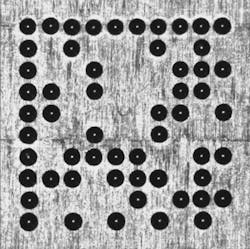
Manufacturers, however, had other ideas. Labels could become defaced or fall off so companies began applying the code directly to the product being identified. Marking parts using methods such as dot peen or laser etching often produces codes with low contrast, poor cell position, or inconsistent cell size. In addition, the surface being marked can be matted, cast, or highly reflective and seldom is as clean and uniform as a white label (Figure 1).
Figure 1. Image of a Dot-Peened Code on a Milled Surface
Until recently, reading such marks has been a challenge. But, advancements in illumination techniques and machine-vision algorithms have permitted development of robust and reliable reading solutions.
The first step toward enabling high read rates is to ensure that the marking process puts down a good code. Although this sounds simple in principle, until now verifying code quality has been both problematic and frustrating. Codes that a reader can easily decipher often failed the verification criteria designed for black-on-white printing.
The recently approved Association for Automated Identification and Mobility (AIM) Direct Part Mark (DPM) Quality Guideline DPM-1-2006 is intended to handle the variety of marking techniques and part materials used in DPM applications.
Marking Techniques
Manufacturers can mark parts with dot peening, lasers, electrochemical etching, and ink-jet printing. Each technique addresses certain applications depending on part life expectancy, material composition, likely environmental wear and tear, and production volume. Surface texture also influences the choice as does the amount of data that the mark needs to contain, the available space for printing, and the mark�s location.
Dot Peening
With dot peening, a carbide or diamond-tipped stylus pneumatically or electromechanically strikes the material surface. Some situations may require preparing the surface before marking to make the result more legible.
A reader adjusts lighting angles to enhance contrast between the indentations forming the symbol and the part surface. The method�s success depends on assuring adequate dot size and shape by following prescribed maintenance procedures on the marker and monitoring the stylus tip for excessive wear. The automotive and aerospace industries tend to use this approach.
Laser Marking
In laser marking, the laser heats tiny points on the part�s surface, causing them to melt, vaporize, or otherwise change to leave the mark. This technique can produce either round or square matrix elements. For dense information content, most users prefer squares.
Success depends on the interaction between the laser and the part�s surface material. Laser marking offers high speed, consistency, and high precision, an ideal combination for the semiconductor, electronics, and medical-device industries.
Electrochemical Etching
Electrochemical etching (ECE) produces marks by oxidizing surface metal through a stencil. The marker sandwiches a stencil between the part surface and a pad soaked with electrolyte. A low-voltage current does the rest. ECE works well with round surfaces and stress-sensitive parts including jet engine, automobile, and medical-device components.
Ink-Jet Printers
Ink-jet printers for DPMs work the same way as PC printers. They precisely propel ink droplets to the part surface. The fluid of the ink evaporates, leaving the marks behind. Ink-jet marking may require preparing the part�s surface in advance so the mark will not degrade over time. Its advantages include fast marking for moving parts and very good contrast.
In all cases, manufacturers should put a clear zone around the mark whenever possible so features, part edges, noise, or other interference do not come in contact with the code.
The range of DPM techniques means that the appearance of the marks can vary dramatically from one situation to the next. In addition to the marking method, the parts come in different colors or shapes and can be made from different materials. Surfaces include smooth and shiny, furrowed, striped, streaked, or coarse granular. Any verification method must provide reliable and consistent results under all conditions.
Verification: The Old Way
Until now, end users of DPM applications had limited options for determining mark quality. The ISO/IEC 16022 international specification defined how to print or mark a Data Matrix code that included the code structure, symbol formats, and decoding algorithms. Although 16022 originally included a few quality metrics, its authors never intended it to address verification. That job was left to ISO/IEC 15415, which emerged about five years later.
Because 15415 assumed black marks on high-contrast white labels, it defined only one lighting method. Verifying many DPMs while observing that constraint would be like sending a photographer into a dark room to take a picture without a flash. If the lighting is inadequate for the verifier to capture a good image, none of the metrics used to evaluate mark quality makes sense.
The 15415 standard requires calibrating the verifier prior to use with a card exhibiting known white values such as a NIST-certified calibration card. Calibration involved adjusting imaging-system settings like camera exposure or gain so the observed white values on the calibration card corresponded to the known values.
Once calibrated, these settings, including the lighting characteristics, never change regardless of marking method, material, or surface characteristics. Again, such a requirement may yield acceptable images for paper labels. Fixed settings for DPM parts, however, produce images that, in most cases, are either under or overexposed depending on the marking method and the part�s reflectivity.
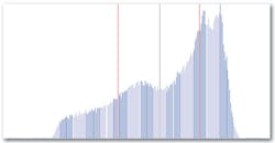
Verification of a code includes analyzing a histogram of that code. Each pixel in an image acquired by an 8-bit camera can have any of 256 gray values. The histogram graphically depicts the number of pixels in the image at each possible gray value, providing a picture of how the values are distributed (Figure 2).
Figure 2. Histogram Showing Gray-Scale Values of All Pixels in the Symbol
The histogram of a well-marked code should show two distinct and well-separated peaks. Without distinct peaks, distinguishing 1s from 0s and therefore decoding the information become more difficult, like trying to read road signs while driving in the rain.
One common problem arises with DPMs when you apply the single lighting configuration of the 15415 standard along with the mandated fixed camera settings: The image looks more like gray on black than black on white. The resulting histogram peaks appear much less distinct.
One standard evaluation criterion is symbol contrast, the spread in histogram values between the lowest (black) and the highest (white). Using fixed settings on DPMs shifts the white far down the measurement scale, producing low-contrast scores and failing grades. A standard auto-exposure routine to optimize the light reflected off the part is needed.
A Standard for the Real World
Even with an optimal image, another problem crops up when analyzing the histograms in 15415. Because they are created by independent processes, histograms of actual DPM codes generally do not exhibit equal-sized or symmetric distributions for foreground and background. So how do you distinguish between the two areas?
ISO/IEC 15415 relied on an overly simplistic method based on the midpoint between the histogram�s darkest value (minimum reflectance) and its brightest value (maximum reflectance). Of course, this method would only yield the correct threshold if distribution of both peaks were identical�which never happens, not even for paper labels.
This problem is exacerbated if you include all of the pixels in the symbol region. Ideally, an image of a good code contains only three types of gray-value distributions: foreground, background, and edges. Edge pixels divide the foreground from the background (Figure 3).
Figure 3. Close-Up of a Single Dot in the Symbol
The gray values in this region change rapidly. As you move across it, they transition from the background bright value to the foreground dark value. The edge pixels contribute to the histogram region between the two peaks, leaving the peaks less distinct than they should be, potentially compromising any information extracted from the code.
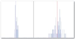
Using information only from the center of the foreground and background modules yields a grid-center image. The histogram that corresponds to such an image, a grid-center histogram, contains no edge pixels (Figure 4).
Figure 4. Histogram of Only the Centers of Each of the Dots in the Code
An additional image-processing step consists of applying a low-pass filter, referred to as a synthetic aperture, with an aperture size that is a certain fraction of the nominal cell size. Using a synthetic aperture prior to computing the grid-center histogram helps to make the grid-center pixels more representative of the actual module by eliminating hot spots and background noise such as machining marks.
A simple yet elegant algorithm to determine the correct threshold examines every gray-scale value from the grid-center histogram, calculating the variance to its left and its right. The point where the sum of those two variances reaches a minimum represents the optimum separation point between the foreground and background peaks.
ISO/IEC 15415 also established a fixed synthetic aperture depending on the application, determined by the smallest module size that the application encountered. The synthetic aperture was created to connect dots of a dot-peen code so that they appeared joined after binarization (Figure 5). Although this approach was not optimal in achieving that goal, it provided other benefits such as reducing hot spots.
Figure 5. Binarized Image Having Values Only 1 or 0
Nevertheless, the synthetic aperture should not remain fixed but rather take on an appropriate value for each mark being verified. Two values were selected for the new standard because marks and surfaces that create a significant amount of background noise, like dot-peen codes on a cast surface, work better with a larger aperture. Smaller apertures better address the requirements of well-marked codes.
Determining optimal aperture size is difficult. Based on empirical analysis, two values were selected: 50% and 80% of nominal cell size. The nominal cell size changes from mark to mark so the synthetic apertures were dynamic instead of fixed as in 15415. The manufacturer performs the entire verification process with both aperture sizes and selects the one that produces the better result.
The optimal image was obtained using an iterative process by analyzing the grid center histogram after applying the synthetic aperture. The imaging system was adjusted iteratively so the mean of the bright pixels would approach an empirically determined value of 200 or �10% on an 8-bit gray-scale camera.
This approach works regardless of the marking method, material, or surface characteristics. The camera settings may not be the same across marks, but it takes only milliseconds to adjust to the proper dynamic range for the camera. Once the optimal image is obtained, the metrics must determine the mark�s quality.
Some marks may require extreme light energy for this process to succeed. The minimum-reflectance metric was created to track this aspect. The metric is graded based on the light energy required to adjust the bright pixel mean to 200 compared to the light energy required for a standardized white target such as a NIST calibration card.
Standard Verification Metrics
ISO/IEC 15415 took a significant leap in the right direction. It contained a number of good metrics. However, the inflexibility of the surrounding conditions reduced their usefulness. The computation methods for these metrics also exhibited limitations that would create problems for both DPMs and paper labels.
The following metrics and methods comprise the AIM DPM standard for assessing a mark�s overall quality:
� Decodability: This pass/fail metric uses a reference-decoding algorithm that the AIM DPM standard has improved to address and decode marks that have disconnected finder patterns. The reference decode algorithm is responsible for establishing the grid center points required for verification.
� Cell Contrast (CC): The name changed from symbol contrast in 15415 to reflect significant differences in what it measures. Instead of determining differences between the brightest and darkest values that are highly variable, CC measures the difference between their means. The capability to distinguish between a black and a white cell depends on the closeness of the two distributions in the histogram.
� Cell Modulation (CM): A well-marked code requires a tight distribution for both light and dark values. If the standard deviation of each peak increases, some center points will approach the threshold and may even cross over. CM analyzes the grid center points within the data region to determine the proximity of the gray-scale value to the global threshold after considering the amount of error correction available in the code. Typical problems that lead to poor modulation include print growth and poor dot position.
� Fixed Pattern Damage (FPD): This metric resembles cell modulation, but instead of looking at the data region itself, it analyzes the finder L and clocking patterns as well as the quiet zone around the code. The first step in reading a code is finding it. Problems with the finder pattern or the quiet zone will reduce the fixed-pattern damage score.
� Grid Nonuniformity (GNU): This qualifies the module placement by comparing to a nominal evenly spaced grid.
� Axial Nonuniformity (ANU): This describes the module�s squareness.
� Unused Error Correction (UEC): Data Matrix incorporates Reed/Solomon error correction. Every grid center point should fall on the correct side of the global threshold. If so, the binarized image will look like a perfect black-and-white representation of the code.
It is not uncommon for some center points to fall on the wrong side. Any such bit is considered a bit error that requires processing through the Reed/Solomon algorithm. The amount of error correction increases with the number of bit errors.
A perfect mark that requires no error correction would achieve a UEC score of 100%. The more error correction, the lower the UEC score. A code with a score of 0 would not be readable with one additional bit error.
� Minimum Reflectance (MR): The NIST-traceable card used to calibrate the system creates a reflectance value. The image brightness is adjusted on a new part, after which this calibrated value is compared with the reflectance of that part.
Parts that are less reflective than the NIST standard card will need more light energy for the camera to achieve the appropriate image brightness. MR is the ratio of the part�s reflectance to the calibrated reflectance. Every part must provide at least some minimum level of reflectance.
� Final Grade: Like ISO/IEC 15415, the code�s final grade is the lowest of the individual metrics. Because the grading system uses letter grades, users often feel compelled to achieve the best possible grade. In this case, however, grades of D or better denote perfectly readable codes. In fact, most readers on the market today can reliably read codes graded F.
Companies that demand grades of, for example, B or better are incurring very high additional costs with little benefit. When using the AIM DPM guideline, we recommend passing marks that score C or better and pass but investigate any code that gets a D.
About the Author
Carl Gerst is the senior director and business unit manager for ID Products at Cognex. Before joining the company seven years ago, he worked for Hand Held Products for 10 years where he held positions in engineering, sales, and product marketing. Mr. Gerst received a bachelor�s degree in electrical engineering from Clarkson University and an MBA from the University of Rochester Simon School. Cognex, 1 Vision Dr., Natick, MA 01760; e-mail: [email protected]
FOR MORE INFORMATION
on the DPM standard
www.rsleads.com/706ee-206
June 2007

