When you buy most large-ticket items, generally there is some rating that helps you understand how well the product meets energy-efficiency standards. In cars, you can look for an EPA miles/gallon rating; with major household appliances, you look for the EnergyGuide label for additional information.
But what if you want to design a solar-heating system? There are similar parameters to help you compare solar collectors. But performing the tests to determine their values is more complicated than you might think.
Such information isn’t just useful in making comparisons. It also can be crucial if you wish to take advantage of federal and state tax benefits. For instance, the U.S. Energy Star tax credit for systems used for solar water heating dictates that you can take a credit for 30% of the system’s cost only if its key components are certified by the Solar Rating and Certification Corp. (SRCC).
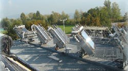
Solar Collector Test Beds Tracking the Position of the Sun at the SPF Institute at HSR
SRCC Certification
SRCC was incorporated in 1980 as a nonprofit organization whose primary purpose is the development and implementation of certification programs and national rating standards for solar-energy equipment. A similar program in Europe is Solar Keymark, formed to address the consistency among individual states’ testing requirements and approach to rating solar equipment.
The SRCC itself does not perform solar-panel testing. Rather, it sets up operating guidelines, test methods, and minimum standards and rating methodologies that independent laboratories use to achieve SRCC certification.
The first such independent test facility, the Florida Solar Energy Center, was accredited in 1980, followed by the first Canadian center, Exova Canada, in 1984. Those two were the only independent test laboratories for more than 20 years and enjoyed a pleasant monopoly.
The energy crisis and the introduction of tax credits encouraged many manufacturers to develop constantly improving solar collectors. But to be viable on the market, these products had to be SRCC certified by either of these two labs.
According to some sources, the waiting list for getting collectors certified has sometimes extended beyond two years. This wait is untenable for panel manufacturers that want to get product to market, especially given that the testing process itself can take six months or longer.
As a result, in the summer of 2009, SRCC gave its accreditation to seven additional testing labs—none in the United States but six in Germany and one in Switzerland. These labs are all now quite busy and performing testing services for manufacturers around the world, including the United States.
What, exactly, is involved in testing solar collectors? To find out, I visited one of these newly accredited facilities: the Solartechnik Prüfung Forschung (SPF Institute) at the University of Applied Sciences in Rapperswil (HSR) in Switzerland. Like the other test labs, it certifies panels to SRCC Standard 100-081 as well as the international equivalents ISO 9806-2 Test Methods for Solar Collectors—Part 2: Qualification Test Procedures and EN 12975 Thermal Solar Systems and Their Components—Collectors.
Unlike with a car or refrigerator, the result is a set of parameters describing the collector performance under different conditions. The effective yield of a solar collector depends on many factors: location, ambient temperatures, local topography, number of hours of sunlight, the direction and angle at which the collector is mounted, energetic quality of the building, and user profiles.
Operational Basics
The basic principles of solar collectors are quite simple and well understood. In flat-panel collectors, sun passes through a transparent cover to enter an enclosed chamber that houses tubes usually welded to the rear side of a specially coated high-absorbing copper or aluminum sheet. The sunlight heats the absorber, and the heat is passed to a fluid that carries the energy to a storage mechanism in the building.
An alternative is the evacuated tube collector (ETC) where the absorber is enclosed in a glass tube under vacuum to prevent heat losses. ETCs are especially popular in the Far East and recently in the Western Hemisphere. There is a lively discussion about the pros and cons of flat-plate collectors vs. ETCs. The best approach to getting a good collector is to buy only tested and certified products.
Despite their functional simplicity, solar collectors can be optimized for given applications. Many aspects during manufacture can be changed to affect performance. For instance, noted Dr. Andreas Bohren, head of testing at the SPF Institute, sometimes it’s possible to have a panel that works too well. If it creates more heat than the system requires, heat builds up in the energy reservoir. In this case, the water reaches the boiling temperature and creates problems.
A critical aspect is the choice of materials for the various components as well as their physical arrangement. Consider, for instance, the coatings that collect and transfer the heat. They can be very inexpensive to very high quality, vary in which frequencies of light they respond to, and have a high absorption factor. A low emission factor is desirable but more difficult to achieve. Consequently, manufacturers use a wide variety of methods and materials to come up with panels best suited to specific applications, but they all undergo the same testing procedures.
Matters are complicated because the tests must be conducted under very exacting conditions. For instance, there must be a certain amount of correct sunlight. It’s understandable that clouds can complicate the situation. But even on a day you or I would consider sunny and suitable for collector testing, there might be too much haze and accordingly too much dispersed light so tests can’t be conducted. There can only be a slight breeze because a high wind will cool off the collectors and distort test results.
All in all, Dr. Bohren estimates there are about 100 perfect testing days per year at his facility. On such a day, the motto is: Out of the office and onto the roof to conduct the tests. This also means that the test setup must always be in operating condition because an equipment failure could reduce the already limited number of testing days.
The Key Parameters
The key parameters being measured, according to Dr. Bohren, define the efficiency curve, the panel’s heat capacity (how long does it take before the panel starts working?), and the incident angle modifier (IAM). These values then are put into simulation software that helps engineers determine the suitability of a given collector for a specific building and application.
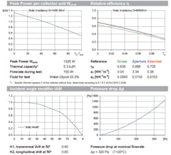
Figure 1 shows the key parameters for a typical solar collector. In the peak power curve (upper left), a collector provides the most power when the ambient temperature and average temperature (Tm) are the same and there are practically no thermal losses. For a normal system, though, this situation is rarely the case, leading to lower efficiency in practice.
The performance curves indicated on the upper right of Figure 1 are more scientific but a less user-friendly representation of the same parameters. Here the performance is indicated per area. On the curve of relative efficiency, the conversion factor ?0 equals the collector’s maximum efficiency. It varies with factors such as the absorber’s coating, thickness and material, the connection between the absorber plate and the fluid pipes, absorber pitch, geometric layout of the pipes, transmission through the glazing, and type of flow in the pipes. It’s incorrect to compare the efficiency of different collectors on the basis of only ?0 since this again represents the working point where the collector is operating at ambient temperature.
In this same plot, the heat-transmission coefficient a1describes thermal losses; the higher its value, the more losses the collector has. A high value means the curve falls more steeply so a lower value is better. Aspects that define this value include thermal insulation, distance between the absorber and glazing, thermal bridging, layout of the fixing elements of the absorber and attachments, and the absorber coating.
Next, a2 is needed to calculate the coefficient of heat transmission, which is dependent on temperature. Its value describes the plot’s curvature. You want as little drop-off as possible, so a lower value is preferable. Factors that contribute to a2 include the absorber’s emissivity and mechanical deformations at higher temperatures. Some standards don’t refer to a2 because modern collectors with selective coating normally display very low values, and quite often it’s accurate enough to simply neglect a2.
The third graph (lower left) plots the incident angle modifier, which describes how collector efficiency changes if the sun shines on it at a certain angle. The values in the first two plots are obtained with vertical solar irradiation. Given that almost all collectors are installed in a fixed manner and most of the time not ideally oriented to the sun, vertical irradiation is quite rare. As a result, the IAM represents a very important parameter when it comes to computing a collector’s overall annual yield.
The final plot (lower right) describes the pressure drop from the entrance to the exit for a given flow rate. This is needed to help size the pump for a system made of multiple collectors; to save electricity you want the smallest pump that can do the job.
The pressure drop depends on the geometry of the collector elements/tubes through which the fluid passes. The loss of pressure generally is lower with harp-type collectors and higher with meandered collectors. A somewhat larger pressure drop often is acceptable. Collector efficiency can be increased because, with laminar flow, the transmission of heat from the absorber to the fluid is lower compared to that with turbulent flow, which increases the pressure drop.
Testing Operating Parameters
To determine these values, the collector is put into constant operation for a specific period of time at precisely regulated diverse temperatures. During this time, the input and output temperature, the ambient temperature, irradiation, and the flow rate are measured in the collector and recorded. From this data, ?0, a1, and a2 are obtained. To determine the IAM curve, the collector is maintained in a specific condition of continuous operation, and it is activated with the desired angles toward the sun’s direction.
Besides measuring the temperature of incoming and exiting fluids, thermocouples are embedded within the enclosed collectors to track the interior temperature. Fluid flow through the collector is measured with magnetic inductive flow sensors.
Keeping thermocouples in calibration isn’t difficult, but the flow sensors are temperature dependent and need special calibration. Dr. Bohren claims that his group is the only one that calibrates flow sensors on a regular basis over the entire range for normal operation in ambients up to 100°C, and they do so with a custom-built calibration setup.
Thermocouples also help measure the collector’s time constant, another important parameter. It reflects the time before the outlet fluid temperature reaches 63.2% of its steady-state value following a step change in the input. This is needed for the previous performance tests because all key parameters must be held steady for 8 x ? for a valid datapoint.
This is particularly tricky because mass flow must be held to within ±1% to account for variations in fluid density with temperature, irradiation must be steady within ±50 W/m2, the outdoor ambient temperature must not vary more than ±1.5 K, and the inlet temperature must be within ±0.1 K for the entire test period. Given that the time constant for a flat-panel collector can be 60 to 100 seconds, these values must be held steady for test times approaching 15 minutes. Moreover, evacuated tube collectors can have a time constant of up to 600 seconds, requiring a test time of 80 minutes for a single datapoint.
However, some of these parameters, such as irradiance and outdoor temperature, cannot be controlled, and the test engineer is at the mercy of Mother Nature. Wind must be monitored, and if it is too high, the corresponding data is not considered valid for testing and removed from the datasets. The minimum amount of irradiation is 800 W/m2, and if there is greater than 20% diffuse radiation, data is once again void.
Even if wind and diffuse irradiation don’t exceed the peak allowed values, the trickiest part is maintaining a fluid at a constant inlet temperature. The method of doing so is to mix cold fluid with hot fluid exiting from the collector. However, this scheme alone reacts too slowly to real-world changes and requires the addition of an electric heater.
As a result, the test engineers have developed a sophisticated control system that consists of three PID loops: the first controls a valve that regulates the flow of hot fluid going into a fluid mixer, a second controls the amount of cold fluid entering the mixer, and the third controls a heating element to fine-tune the temperature of the fluid entering the collector. These three loops must interact without the system going into oscillation. Due to the high temperature constants in thermodynamic systems, it sometimes can take an entire day to get the proper loop parameters set.
Durability Testing
A second set of tests verifies durability. After all, manufacturers claim and users expect a service lifetime exceeding 20 years. During those years, the materials are put under extreme conditions in the presence of UV light with great temperature cycling in various environments of wind, rain, dust, snow, and ice.
One important test checks the stagnation temperature, which is the maximum temperature the collector’s absorber reaches an ambient temperature of 30°C and an irradiation of 1,000 W/2. It’s also a measure of the collector’s thermal losses and, for that reason, connected to the efficiency curves.
However, you should consider that a high stagnation temperature causes great wear on materials. Depending on the application, it might be wise not to select the highest performing collector but one with modest stagnation temperature to reduce the thermal load on the materials.
Similarly, a long-term exposure test serves as an indicator of problem issues that might arise over the collector’s service lifetime. In this test, a collector is exposed to radiant energy of at least 14 MJ/2; over a period of 30 days. The requirements in the United States are for 17 MJ/2. In addition, for at least 30 hours the radiation level must exceed 850 W/m2 in an ambient of at least 10°C. The most frequent problems that arise in this test are outgassing from insulation, glues, sealants, and gaskets and deformation of the absorber or the glazing.
A similar test determines whether collector materials can withstand the expected mechanical forces that arise during peak temperatures. The collector, not filled with fluid, is set in an ambient between 20°C to 40°C with low wind velocity and then exposed to irradiation of 1,000 W/m2
Other durability tests are likewise generally straight forward. For example, one test places a collector under pressure to see if it drops by a certain amount in a specific time. For this, only pressure gages are needed.
Internal/external thermal shock tests also are direct. Here a collector containing no fluid is placed in high incident solar radiation and ambient temperature. For an internal test, cold water is flushed through the collector, which then is examined for damage such as cracks or leaks. For an external test, the unfilled hot collector is subjected to a cold water bath for 15 minutes in an ambient temperature >10°C.
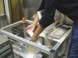
Two additional special tests are required to get the SPF quality label, and they examine the effects of falling rocks or hailstones. A 150-gram ball of ice is either dropped from a height of from 0.4 m to 2.0 m or, in the case of the SPF, it is launched through a custom apparatus (Figure 2). Interestingly, this test setup is based on a modified baseball pitching machine to propel the ice balls.
Figure 2. Loading an Ice Ball Into a Customized Launcher to Test the Durability of Solar Panels Against Hailstorms
Issues of Pyranometer Calibration
In any solar testing, a key sensor is the pyranometer, which measures total solar flux density for direct, diffuse, and reflected radiation. Suppliers of such instruments include Hukseflux, EKO Instruments, and Eppley Laboratory with one of the biggest names, and the source of the units at the SPF, being Kipp & Zonen.
Ruud Ringoir, product manager of solar radiation at Kipp & Zonen, explained that the selection of a pyranometer depends on the type of solar panel because solar thermal collectors use much more of the spectrum than do photovoltaic panels. Even for solar collectors, depending on the type of concentrator, either a pyranometer or a pyrheliometer is needed for accurate measurement of the received energy.
These instruments are based on a thermopile, which consists of a number of thermocouples in series. Depending on the instrument type, these thermocouples are placed in a circle or used as a Peltier element. When configured in a circle, the hot junctions point toward the center.
Energy on a black surface heats up the sensor, resulting in a temperature gradient from the hot inner circle toward the edge of the black sensor connected to the body of the instrument. This gradient is very small, at most a few degrees for 2,000 W, and it is linear with the energy radiated on the sensor. Thermocouple nonlinearity is compensated for with NTC resistors to get linearity over the operating range between -40°C and +80°C. Two domes are required to isolate the sensor from outside temperature changes, wind, and rain. The unit’s output typically is 15 to 20 mV for 1,000 W/m2.
The sensitivity of each sensor is unique and determined by the manufacturer by comparing it to a standard pyranometer that, in turn, is regularly calibrated by the World Radiation Center (WRC) in Davos, Switzerland. To handle calibration issues, SPF submits a reference pyranometer directly to the WRC for calibration every year, and all the other pyranometers then are calibrated at the SPF.
Many national meteorological centers can perform calibration, but their reference pyranometers can all be traced to the World Radiometric Reference (WRR) in Davos. The WRR is the measurement standard representing the SI unit of irradiance. It was introduced to ensure worldwide homogeneity of solar radiation measurements and has been in use since 1980. The WRR is determined from the weighted mean of the measurements of 15 absolute cavity radiometers that have been fully characterized and has an estimated accuracy of 0.3%.
Critical for System Design
When manufacturers submit their solar collectors to SPF for initial testing, Dr. Bohren estimates a failure rate of 60% to 70%. Frequent problems are the accumulation of humidity; there is always some condensation so ventilation must be properly designed. There also is outgassing that can result in the discoloration of the cover’s glass. He added that most problems can be readily overcome.
But once a collector has been approved, designing a system with it is not as easy as it looks. It’s possible to do many things incorrectly. For instance, a collector might gather too much heat for a given system. If the liquid reaches the boiling point, the result can be significant damage to the collector as well as storage tanks and other components. All elements of a solar system must be sized for the specific application requirements and environment in which it will be placed in service.
To aid system designers, the operating parameters found on datasheets from testing organizations can be entered into special software along with a description of the total system. Such simulators then show what kind of performance you can expect and are a great aid in sizing various components.
References
1. Test Methods and Minimum Standards for Certifying Solar Collectors, February 2008, www.solar-rating.org
2. www.solarenergy.ch


