Semiconductor manufacturers continue to look for ways to reduce the cost of test for producing mixed-signal SOC and SIP devices. Parallel test strategies, known as multisite test, implemented on ATE have grown from two sites a few years ago to eight or more sites today.
Looking into the future, continued increase in site count will encounter some significant challenges. For example, the amount of device interface board space available to hold the handler device contactors and the applications circuitry for mixed-signal devices is limited. Also, the increased cost associated with adding instruments to the test system configuration can quickly meet diminishing returns as parallel test efficiencies reach levels greater than 95% for short test times.
As a result, the semiconductor manufacturer has turned to its design organization to implement design-for-test techniques to help reduce test costs. The designs of integrated mixed-signal SOC and SIP devices now provide the capability to test each of the building blocks within the device as though they are separate devices.
Accordingly, the blocks of the device have the capability to be tested simultaneously, which is referred to as concurrently. This leads to a new test strategy called concurrent test. When concurrent test is combined with multisite test, significant throughput gains and lower test costs are attainable.
Why Measure Concurrent Test Efficiency
Similar to how parallel test efficiency is measured to determine how effective multisite test is, concurrent test also requires a performance measurement to determine how effectively this new test strategy is implemented. Concurrent test efficiency (CTE) is a means of measuring how well the test strategy is implemented and determining how well the device was designed to support a concurrent test strategy.
A concurrent test implementation known as the concurrent test flow is dependent on several factors. The first and most critical is test access to the individual blocks of the device, which is enabled by the device design. The second issue is the test system architecture and its specific instrument configuration because these can limit the number of activities that occurs simultaneously within the system.
The final factor influencing the amount of CTE achieved comes from the test system’s software capability for implementing a concurrent test flow and how well the test programmer utilizes that capability. This is related to the amount of test development time devoted to the concurrent test implementation, especially if the software system does not provide features to make this task easier for the test engineer.
Process for Concurrent Test Flow Development
Before reviewing the equation for CTE measurement, it is important to understand the process for developing a concurrent test program. The typical process entails four steps:
•?Single-site serial test flow
•?Multisite serial test flow
•?Single-site concurrent test flow
•?Multisite concurrent test flow
The first step is to establish the serial test flow for single-site operation to ensure the device interface board is working properly, provide a simpler environment to debug the tests and device functionality, and make certain that test results correlate to a defined reference standard.
As is typical for test program development, next is implementing the multisite flow. This ensures all test sites are working correctly on the device interface board.
Once this is accomplished, the third and most challenging step is to implement a concurrent test flow for a single site. This can be very time-consuming. It could require the engineer to rewrite the entire program unless the tester’s software allows the programmer to create a concurrent test flow directly with the tests used in the serial test flow.
When the same test code is used between the serial and concurrent test flows, it is much easier to determine if a concurrent test problem is associated with the device or if the problem is associated with the test program code. In fact, being able to use the same test code in both a serial test flow and a concurrent test flow significantly reduces implementation time and makes debugging and maintaining the test program much easier over the long run.
Once the concurrent test flow is established for single-site operation, the final step is to ensure the concurrent test flow works in the multisite environment. Each of these steps creates a methodical process to establish a high-throughput, well-correlated concurrent test flow program in a multisite test environment. Throughout the execution of the steps, the same device interface board is used since its initial design objective is to implement concurrent multisite testing.
CTE Measurement
The CTE measurement is based on the test time of serial test flow on a single site. The equation for CTE is as follows:
CTE = 1–{(CTT–ICTT)/(STT–ICTT)}
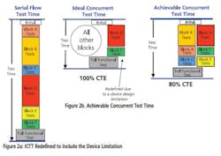
The ICTT is made up of two parts. The first portion of this parameter is the time it takes to execute the portions of the device test program that must operate serially. For example, there may be a requirement to run the device as a complete functional system. This would operate serially relative to the concurrent operation of individual blocks of the device. There also may be an initialization sequence required by the device as well as continuity, leakage, and power supply tests to make sure the device is functional.
The second portion of the ICTT parameter is the amount of time necessary to test the longest block of the device identified from the serial test flow. In the example shown in Figure 1, the serial flow executes Block A followed by Block B, and so on. The ICTT is the sum of the initialize function, functional test, and the tests associated with Block D. Based on the serial test flow, Block D has the longest test time of all device blocks. This example shows a final concurrent test flow achieving 92% efficiency.
The ICTT also needs to include any device limitations that may prevent concurrent operation. For example, it may not be possible to operate scan tests on a device while concurrently testing other blocks because of device power supply issues.
Another typical constraint may be block accessibility. If an operating block in the device can only be accessed through another block or can only operate in conjunction with another block, then concurrent test on the inaccessible block will be limited.
These limitations need to be included when defining the ICTT. In Figure 2a, the ICTT includes the device limitation where Block F has to be tested serially with Block D and the sum of the initialize function and functional test.
Achievable CTE
There also may be limitations caused by the test system’s architecture and configuration. For example, if there are four blocks on the device that can be tested concurrently and have different operating frequencies not related to each other, the tester has to be capable of generating each set of frequencies simultaneously. This requirement is commonly referred to as multiple time domains in the tester.
If the tester only provides two unique time domains, then it will limit the amount of concurrent test that can be implemented and impact the overall achievable CTE. In Figure 2b, the achievable concurrent test time reflects an example where the tester is limited to only providing two time domains and requires the flow shown. In this situation, the best achievable CTE is 80%.
The elements that make up the ICTT as well as the issues that impact the achievable CTE must be clearly understood to determine appropriate improvements and minimize the overall cost of test.
When the test engineer implements the concurrent test program, he will be expected to get as close to the achievable CTE as possible. The ability to do this will be impacted by how easy it is to implement the test program using the tester software and the performance of the tester hardware to perform functions such as capturing DSP data for processing and setting up instruments in parallel.
The more efficient the tester is at performing these functions, the closer the test engineer will be able to get to the achievable CTE. The final CTE will be mostly impacted by how easy the test system software makes the job for the test engineer to implement the concurrent test program.
The SI Ratio
The measurement of CTE needs to be used carefully when determining whether or not to continue investing valuable engineering resources to improve the final CTE. For that reason, understanding the relationship between CTE and throughput improvement can be very helpful.
The impact of CTE change on throughput is dependent on the relationship between STT and ICTT. In fact, the ratio of the STT to ICTT, referred to as the SI ratio, provides a very good indicator of the effect of CTE changes on throughput improvement. The larger the SI ratio, the more impact CTE changes will have on the throughput improvement.
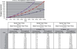
Figure 3 shows how various SI ratios can impact the potential throughput improvement achievable for a variety of CTE values. Throughput improvement becomes more sensitive to changes in CTE as the SI ratio increases. A higher SI ratio indicates there is a greater amount of concurrent test capability in the device. Throughput improvement of 100% is equivalent to half of the test time and produces 2x the number of devices per unit of time.
As higher levels of CTE are achieved, the nonlinear relationship between CTE and throughput improvement shows that small incremental changes to CTE will translate into significant changes in throughput improvement. So if a test program is achieving 50% CTE and has an SI ratio of 3.0, a 10-point improvement in CTE can provide a 17-point increase in throughput improvement.
Summary
There are several key benefits associated with using a consistent, standardized method for measuring CTE. It assists in projecting test times for new devices, determining if additional test engineering effort will provide substantial test time improvements, and comparing the performance of test solutions across multiple device products. It also is a way to measure the implications of potential device design or test system configuration changes to improve the CTE and reduce test times.
The capability to implement a concurrent test program in a short amount of time has the biggest impact on CTE. The easier it is to develop a test program with a reasonable level of efficiency, the quicker reduced test times can be attained for production test and the sooner cost reductions will be realized by the semiconductor manufacturer.
About the Author
Randy Kramer is the manager of Factory Applications Engineering in the Semiconductor Test Division of Teradyne. He has 28 years of experience in the ATE industry. Mr. Kramer received a B.S.E.E. from Rensselaer Polytechnic Institute. Teradyne Semiconductor Test Division, MS 600-3, 600 Riverpark Dr., North Reading, MA 01864, 978-370-2321, e-mail: [email protected]


