The DMM was the first instrument to benefit from computer control. RS-232 initially was used to communicate with DMMs, followed in the mid ‘70s by IEEE 488, which is credited with a long lasting impact on measurement automation. Once minicomputers and later specialized desktop computers were able to control DMMs as well as other instruments, the evolution of test automation was underway.
This moderate progression was violently shaken with the introduction of the PC in the early ‘80s, resulting in an accelerated proliferation of test automation. The rapidly improving cost/performance of PCs created demand for the better targeted computer-based instruments.
The first plug-in DMM was introduced by MetraByte, which later merged with Keithley Instruments. This 4½-digit ISA PCIP DMM was followed by the 5½-digit Signametrics ISA DMMs distributed by Keitheley Instruments. Twenty years later, these units gave way to models compatible with the newer PC interfaces such as PCI, PCIe, PXI, LXI, and USB.
A new phrase, PC-based test, was coined. The reasons for the switchover to these instruments were compelling: integration inside the PC; elimination of extra baggage such as displays, buttons, line cords, and power supplies; and the removal of the extra layer consisting of the IEEE 488 interface card, cables, and software. The result was a streamlined, fast, and reliable alternative to the traditional box instrument.
Software Approaches
To further advance this plug-in concept, a great effort was made to create easier to use installation packages, drivers, and application software. Acknowledging that users are attached to a few favorite software tools with which they are comfortable, some manufacturers elected to create universal drivers. With this type of driver, users could control a DMM from a multitude of packages including MatLab and Microsoft Excel and Word and a large number of programming languages such as Java, C#, FoxPro, C, C++, VB, and LabVIEW.
In addition to the comfort of using familiar tools, the small and agile universal-type drivers allowed users to be up and running in less than five minutes with only the operating system and driver present. Manufacturers having an eye on the software market created drivers targeting only a few packages, mainly their own. These drivers entailed a more complex, large-installation footprint and dependency on additional software items. This resulted in longer, more difficult, and expensive installation but seamless operation with these specific software packages.
Expanding the Basic Measurements
Until recently, DMMs changed very little. The early plug-in units simply carbon copied the box-type DMMs, offering the same repertoire of measurements. But there is more to those basic DMMs.
If your DMM does not include diode test, you can easily add this capability. Using the ohmmeter part, you can test diodes, LEDs, and other semiconductors. The voltage drop will be approximately the multiplication of the test current by the measured resistance. Test currents normally are listed in the manual for each resistance range. Don’t expect better than 5% accuracy since the built-in current sources may be stable but not very accurate.
These selectable current sources also can be used to measure capacitors. Some DMMs have a predictable measurement interval. You can calculate the capacitance by using the basic differential equation
where: dv = difference in resistance from measurement to measurement times the test current
dt = measurement interval
Expect to measure as low a capacitance as 1 or 10 µF with accuracy of about 8%.
Another useful measurement entails the 10-MΩ high-voltage divider, commonly used in DMMs, for current measurement. Due to its high value, it only can be used to measure up to about 20 nA and down to a few picoamps.
Selecting one of the higher DC voltage ranges and dividing the reading by 10M result in the current. Expect accuracy to be better than 2% since this divider network usually is very accurate. Watch out for DMMs that have an auto-zero feature which usually is used to compensate for a drifty front end. It could interfere with this measurement.
There may be a couple of additional hidden measurements that can be jury-rigged, but you are close to the limit of your old DMM. It’s time to take a look at some newer concepts in DMMs.
What More Can a DMM Do?
This new breed of high-performance plug-in DMMs has some noteworthy capabilities that are light-years ahead of their predecessors. Although slightly more expensive, these models incorporate quite a few operations, and one of these may allow you to eliminate the need to include a much more expensive, single-minded piece of gear. Of course, they provide the basic DMM functionality you need anyway.
Being aware of the increased functionality may save the day. After all, a test system that is faster, compact, and versatile is more competitive. More and more test engineers and scientists are turning to these high workload instruments, sometimes only using one or two of their unique features. Since most of the manufacturers offer a 30-day no-risk evaluation period, take advantage of it, check out some DMMs, and become the resident expert on their technology.
What Is So Special About Them?
Many terminator networks incorporate embedded series RCs. Not many instruments can measure those simple networks. Nor can your benchtop DMM do this. Custom or highly specialized test equipment usually is used for this job.
A search will reveal that the SMX2064 PXI DMM from Signametrics can measure both R and C using a two-terminal connection. This instrument also is available in USB format.
Leakage is another test used to evaluate interconnecting cables, PCBs, and semiconductors. Not to be confused with resistance measurement, leakage test requires the measurement of very low current through a device while applying a specific DC voltage to it.
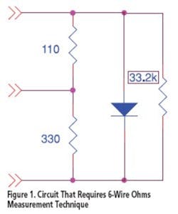
Another special measurement, normally reserved for large in-circuit testers, is the guarded measurement. Suppose we need to measure a 33.2-kΩ resistor, but it is burdened with various other components including low parallel resistance made up of two resistors connected in series. One is 110 Ω and the other 330 Ω (Figure 1). This is not an unusual circuit, but few instruments can handle it.
To do so, you need a 6-wire connection referred to as 6-wire ohms or use a three-terminal connection. The DMM floats the junction of the two low-value resistors by guarding it to a level that prevents the test current of the ohmmeter from being shunted away from the 33.2 kΩ. This nearly eliminates the effect of the load on the higher value resistor you are trying to measure. With some imagination, this test can be carried to other similar topologies and networks.
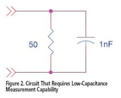
Several DMMs can measure capacitance but not as quickly and certainly not loaded capacitors. Nor can they measure down to 1 pF. The SMU2064 actually has two engines. One uses a network analyzer and can measure burdened capacitance down to about 50 Ω in parallel (Figure 2). The other is a charge-balance method, which is very fast and accurate but can’t tolerate significant burden.
We can take this a step further. Since this type of DMM can measure both capacitance and inductance, it lends itself to making transmission line characteristic impedance measurements.
Some traditional DMMs include a frequency counter; however, they can only handle signals with a duty cycle of around 50%. Unfortunately, most signals we need to measure have a different duty cycle. Some of the advanced models solve this problem by including a variable-threshold DAC capable of ±5 mV to ±400 V. A variable threshold improves measuring the frequency of lower amplitude signals.
In addition to the standard features, typical instruments in this class can have extensive hardware and software triggers, accommodate a component handler interface, measure pulse width and duty cycle, make totalizer/event counter measurements, and provide ±10 V and ±24 mA source/measure capabilities.
Alternatives Can Make Life More Complicated But Rewarding
A large manufacturer of gaming computer boards had a prohibitively costly problem. It manufactures an assembly that includes a thermoelectric-cooling Peltier device. Many of these fragile and expensive devices were damaged during assembly. Fortunately, imminent damage is manifested by a minute shift in the device’s resistance. However, a 5% shift in a nominal 1-Ω resistance translates to 50-mΩ variation.
No problem; it can be monitored with a standard DMM using a 4-wire ohm configuration. The test engineers tried this, and the results were marginal in the lab but unacceptable on the manufacturing floor. They observed too much measurement drift.
This is not all that surprising. Measuring less than a 50-mΩ shift requires a very sensitive DMM, preferably one with high dynamic range— high A/D counts, not just digits—and more than the standard 1-mA test current. It also requires instrumentation-quality multiplexers if multiple devices are tested.
A Peltier device has a nasty DC voltage that can be higher than the test voltage. For this reason, manufacturers of Peltier coolers recommend using AC-based resistance measurement. This can overcome the device’s inherent source voltage, and if using a switching module, this also will reduce its thermal offset voltage.
The Signametrics SMU2064 was selected for its capability to measure AC-based resistance. However, to measure such a small resistance variation requires significant AC stimulus. This leads to device heating and cooling and further variation in the device’s inherent voltaic behavior. So this second approach was an improvement, but not that great either.
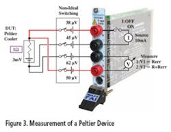
At the end of the day, it was decided to use a 4-wire range with 10-mA test current. Further, the offset ohms mode was enabled. At this higher current level, the measurement sensitivity was 10 times greater while the offset ohms neutralized the device’s parasitic voltage (Figure 3).
On the production floor, things got back on track, and the losses associated with destroying expensive devices were reduced. This change was implemented without impact on production throughput. Payback for this test system was less than a week.
Myths and Legends of Switching
Since plug-in DMMs are mainly associated with automated test systems, it is natural that their terminals are routed to multiple measurement points by means of switching. This is significant because it is like feeding a 10″ diameter pipe by a ½” pipe and expecting 10″ flow. This is such a common myth that it is worth digressing to make a couple of observations about the consequences of combining DMMs and switches.
A multiplexer or most other types of switches have characteristics that can present a real challenge. Use the wrong switch, and you will see significant error, particularly when measuring low-level signals such as in thermocouples and RTDs. This error usually manifests itself as a large measurement error that drifts in time without any clue as to its source. The majority of plug-in switches on the market are prone to this.
The phenomenon causing this error is not related to contact resistance of the switches, nor can it be reduced by using a Kelvin 4-wire connection. It is referred to as thermoelectric or thermal EMF, also known as Thomson, Seebeck, or Peltier effects, and is caused by dissimilar metals and caloric difference.
Each closed contact in a signal path connected to a measuring instrument must be considered a small voltage source. Let’s quantify this by an example. Assume a garden-variety switch with total 100-µV path thermal EMF is connected to a common DMM having a 1-mA test current in resistance mode. Using Ohms law, the error contributed by the switch is ±100 mΩ. This is unacceptable in many applications, including in the Peltier example.
Compare this to the use of an instrumentation-quality switch with less than 3 µV of thermal offset but with a DMM with 10-mA test current. Now the total error is only ±0.3 mΩ. And yes, we did check the math, and it is 1/300th of the error.
Conclusion
Today’s high-power DMMs introduce extensive functionality in our test systems. Being small and cost-effective and having computer interfaces make them a good choice for the new generation of test systems. While traditional units were categorized in terms of their digits, these newer units are distinguished in terms of their capacity to source and measure. For these reasons, they are showing up in test applications not commonly associated with DMMs, bridging the gap between conventional DMMs and specialized test equipment.
About the Author
Tee Sheffer is the president and founder of Signametrics. He earned undergraduate and graduate degrees in electrical engineering from the University of Washington. From 1977 until 1990 when he founded Signametrics, Mr. Sheffer was a senior staff engineer and project manager at Fluke. He holds 10 patents in the area of test and measurement and has authored several technical articles. Signametrics, 6073 50th Ave. NE, Seattle, WA 98115, 206-524-4074, e-mail: [email protected]


