EMC is fundamentally about peaceful coexistence: An electrical device must function correctly in the presence of interfering signals and not unduly disturb the environment with its own emissions. Specific emissions and immunity limits are set in the various EN, ETS, ANSI, FCC, VCCI, and CISPR EMC standards.
Depending on the type of equipment, different standards apply. One of the newest is CISPR 22/EN 55022 which becomes effective in October 2010 and mandates radiated disturbance measurements up to 6 GHz for IT equipment sold in the EU. This includes computers, modems, printers, and associated components.
Tests naturally segregate into four categories: conducted or radiated emissions or immunity, also termed susceptibility. The equipment needed to conduct immunity tests includes signal generators, amplifiers, antennas, and field-strength probes. An EMI test receiver or spectrum analyzer is used to measure emissions accurately, and a line impedance stabilization network (LISN) isolates the DUT from the AC supply to facilitate measurement of the DUT conducted emissions. Test sites are equally important, with anechoic chambers favored for immunity testing at high field strengths and open-air test sites (OATS) for emissions.
As the standards change, test equipment specifications must keep up. In fact, test equipment performance generally needs to be ahead of that required by standards to allow for some margin. It also must support development of products that will have to comply with even more rigorous emissions and immunity limits in the future.
Changing technical requirements, however, is only one reason to buy new equipment. Test executive software may save time while also ensuring consistent quality. Sometimes, new models of antennas or amplifiers with extended frequency ranges become available, eliminating the need to perform testing in separate bands. Or, perhaps a failed compliance test has highlighted the need to invest in precompliance test facilities.
New EMC Hardware Benefits
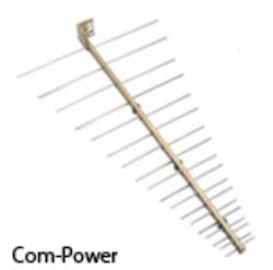
Precompliance Test SystemIn general, a DUT’s chances of passing a full compliance test are greatly improved if it has passed in-house precompliance tests. Engineers have addressed unintended radiation and conduction issues through filtering and shielding or circuit and PCB redesign to meet emission limits. Dealing with these issues before scheduling full compliance testing reduces costs by almost guaranteeing first-try success.
Nevertheless, as Mr. Miranda observed, “Many problems discovered at a commercial test lab require reworking the product to meet the requirements. The test engineer may not have experienced staff present at the lab to troubleshoot, fix, and retest the product. Often the product must be taken back to the factory and the test rescheduled. Precompliance testing at the factory with the PC-114 can reduce the number of required retests.”
Test Receiver
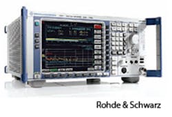
The Model ESC17 is a CISPR 16-1-1-compliant EMI test receiver that R&S introduced to address emissions testing from 9 kHz to 7 GHz. This range exceeds the requirements of the new CISPR 22/EN 55022 standard for IT equipment in the EU. With the receiver’s integrated spectrum analyzer, it can measure phase noise, occupied bandwidth, and adjacent channel power or determine the third-order intercept point.
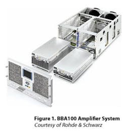
The BBA100 Amplifiers are based on the company’s TV transmitter technology and market experience. For example, three individually configurable safety-interlock circuits in the BBA100 base unit can be assigned to separate RF paths. This feature makes it possible to work on a test setup in one room while testing is being performed in another.
The company’s Mr. Gerstner commented, “The BBA100 makes susceptibility testing easier with the company’s TS9986 Conducted Emissions Test System and expands the test capabilities. Together with a signal generator such as the Model SMC100A and the NRP-Z91 Power Sensors, the BA100 and TS9986 make up a comprehensive test system controlled by EMC32 software.”
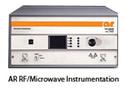
Jason Smith, applications engineering manager at the company, said, “Our S Series microwave solid-state amplifiers with 1-GHz to 4.2-GHz frequency range and up to 800-W output power also were redesigned. As with the A Series, the new design packages more power in a small cabinet. The rugged design maintains the S series’ load tolerance and good linearity.”
The Ophir RF 50-W Model 5193 Broadband RF Amplifier covers the frequency range from 2 GHz to 6 GHz and features ±1.5-dB power flatness and +54-dBm typical third-order intercept (IP3 or TOI). The class A/AB linear power output stage is claimed to provide a wide dynamic range, high gain, and the good TOI point. Circuit protection includes thermal overload, overcurrent, and overvoltage. In addition, models are available with front or rear connectors as well as LAN, GPIB, and RS-232 I/O.
Giga-tronics now has two very wideband power amplifiers, the Model GT-100A with 2-GHz to 20-GHz bandwidth and the more recently released 2-GHz to 50-GHz GT-1050A. According to the GT-1050A datasheet, these amplifiers are based on solid-state parallel MMIC design. The earlier GT-100A model used the Spatium™ Combining Architecture patented by CAP Wireless, a Giga-tronics channel partner.
Transient Test Equipment
Transient testing mimics real-world waveforms to ensure that the EUT can withstand extreme disturbances. Of course, transients can affect the EUT in a number of ways. To account for many of them, waveforms are organized into groups with descriptive names: electrical fast transient (EFT)/burst, impulse magnetic field, AC magnetic field, dips and interrupts, and DC dips.
These disturbances are applied to the power input of the EUT while its performance is monitored. Depending on the application, a brief interruption of operation may be acceptable, assuming that the EUT returns to a fully working state immediately after the disturbance is removed. Generally, it’s not acceptable for the EUT to be damaged by transient testing.
Very fast rising-edge transient pulses followed by a slower and sometimes oscillating falling edge are typical of lightning- or switching-induced power disturbances and used in communications network testing. Combination waves are denoted by 1.2/50 or 8/20, indicating the times in microseconds to rise to the peak and then fall through the 50% level.
Actually, these two ratings describe the output from the same generator. The 1.2/50 numbers relate to the voltage waveform developed across an open circuit and 8/20 to the short-circuit current waveform.
Haefely EMC Technology, located in Switzerland and part of the Hubbell High Voltage Test Business, has developed the compact ECOMPACT4 Transient Immunity Tester that generates six categories of waveforms. According to Brian Bolz, EMC applications engineer, “The tester has an integrated 16-A single-phase coupler/decoupler network (CDN) and dips transformer. A software package is included that allows fully automated testing and test reporting. Additional accessories are available to further extend the tester’s capabilities.”
Mr. Bolz works for Hipotronics, a U.S.-based part of the Hubbell High Voltage Test Business. He commented that microprocessor-based electricity-meter EMC testing has seen an increased demand. Although some new standards have accompanied introduction of the meters, many of the relevant test requirements already existed via IEC-61000-4-x, ANSI C62.41, and C37.90.
“These standards specifically call out combination wave surge, damped oscillatory wave, ring wave, and EFT/burst tests,” he explained. “Haefely’s modular PSURGE8000 Surge Platform System with the PEFT4010 EFT/Burst Test System handles all of these requirements. The system is controlled by the company’s WinFEAT&R Software, which also supports test-report generation.”
The Radi EMC instruments from D.A.R.E!! also are modular. As explained by Rene Dijkstra, the company’s general manager, “PC-controlled one-, two-, and eight-slot RadiCenter chassis accept a range of instruments including the RadiPower RF Power Meters, RadiSwitch Switch Cards, RadiGen RF Signal Generators, ADCs and DACs, optical links, and turntable/mast controllers. Rather than being general-purpose, all of the instruments are designed specifically for use in a cost-effective EMC test system.”
The hardware can be controlled by software packages from other vendors although RadiMation is the preferred application.
Field Probes and Meters
EMC Test Design offers a range of five isotropic probes covering the frequency range from 100 kHz to 18 GHz. Four are broadband, and the fifth allows selection between two bands. The probes can be used with either of the company’s two field meters, the RFP-04 Smart Fieldmeter® or the RFP-05 Smart Fieldmeter Digital. In addition, the GPS-R GPS position receiver when used with the Smart Fieldmeter Digital provides position logging together with stored field strength information and a time/date stamp.
New EMC Software Benefits
According to Glen Watkins at ETS-Lindgren, “The company’s TILE! Software provides the flexibility to design test sequences with drag-and-drop simplicity in a Windows environment or use predefined templates for typical radiated and conducted immunity and emissions testing. Adding to TILE!’s flexibility is the capability to integrate new and existing instrumentation from most first- and second-tier manufacturers; more than 1,500 equipment drivers are available, and the number is growing.”
A recent development in which TILE! featured prominently involved integration of a commercial test house’s existing legacy EMC equipment together with new instrumentation from a variety of vendors. In addition, ETS-Lindgren provided the test chamber and antennas. TILE! manages the complex collection of hardware, ensuring that tests are performed in accordance with international EMC standards for commercial, medical, and military applications.
Explicit Modularity
Another comprehensive EMC application, actually a suite of applications, is available from Teseq. The Compliance 3 Software Suite comprises Compliance 3 RF Emission, Compliance 3 RF Immunity, Emipak 3 Precompliance Emission testing, and GTEM 3 RF Emission/Immunity programs.
Teseq describes the Compliance 3 Software Suite as a high-level graphical programming language so you can expect to quickly develop new test sequences without a lot of low-level programming. Many instrument drivers are included as well as RS-232, GPIB, and USB interfaces. In addition, you can choose or modify routines from a library of predefined tests for commercial, military, automotive, telecommunications, aerospace, and medical applications.
The R&S EMC32-EMC Measurement Software also is modular and based on a graphical operating concept. As you might suspect, the emphasis is on compatibility with R&S test receivers and spectrum analyzers. Drivers are included for a large number of accessories such as mast and turntable systems.
EMC32-S is the module that supports susceptibility testing, EMC32-K10 is for fully automated EMI testing when combined with EMC32-EB EMI Measurement Software, and EMC32-K11 together with the –S or –EB module allows individual measurements to be combined into a complete test sequence. The company’s brochure describes the software as being “for manual and partly automated disturbance measurements in R&D and conformance testing.”
RadiMation EMC Control Software is the preferred package for use with D.A.R.E!! Radi EMC hardware and offers multivendor support for other instrument brands. Mr. Dijkstra commented, “Using the RadiMation Software and Radi-instruments, complete test systems have been built all over the world. In cooperation with our network of system integrators, we have implemented complete test systems for leading automotive suppliers and other industrial and governmental laboratories.
“The main advantages of our system are the flexibility and the multivendor support,” he continued. “This combination as well as the overall cost-effectiveness are major benefits of the systems.”
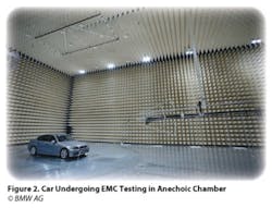
The large EMC test chamber shown in Figure 2 uses D.A.R.E!! instruments and RadiMation software, configured by emv GmbH. Similar smaller chambers have been constructed by other system integrators using D.A.R.E!! modular instruments and control software.Summary
If you regularly conduct EMC emissions and immunity tests, you probably have most of the necessary equipment. In this case, the biggest challenge is to keep up to date with changes in standards and ensure that your test instrumentation and methods comply. It’s relatively straightforward to identify a new amplifier or software package that will improve what you already have been doing.
A far more daunting challenge is to find the optimum mix of test environment, equipment, and software if you lack current test background. In this situation, consulting an experienced test-systems integrator often is helpful. In addition to experience, such a company also has built good working relationships with instrumentation OEMs. System integrators may make solutions available that you weren’t aware of or that simply would be impractical to develop without the integrator’s involvement.
Conceptually, EMC testing is not difficult. Nevertheless, details like interfering sources, differences among similar international standards, and even measurement uncertainties and correction factors soon complicate the process. Minimizing measurement complexity is one of the major advantages of new equipment such as the Giga-tronics GT-1050A 2-GHz to 50-GHz Broadband Amplifier. Similarly, vendor-agnostic software such as ETS-Lindgren’s TILE! and RadiMation from D.A.R.E!! simplify interfacing to equipment from multiple manufacturers.
Changing standards, increased efficiency, and reduced measurement uncertainty are common reasons to update equipment and software. The good news is that many new or improved instruments and applications are available.
| FOR MORE INFORMATION | Click below | |
| AR RF/Microwave Instrumentation | A Series Amplifiers | Click here |
| Com-Power | PC-114 Precompliance Test System | Click here |
| D.A.R.E!! | RadiMation EMC Test Software | Click here |
| EMC Test Design | Smart Fieldmeter Digital | Click here |
| ETS-Lindgren | TILE! EMC Test Software | Click here |
| Giga-tronics | GT-1050A Broadband Amplifier | Click here |
| Haefely EMC Technology | ECOMPACT4 Transient Immunity Tester | Click here |
| Ophir RF | Model 5193 Broadband Amplifier | Click here |
| Rohde & Schwarz | BBA100 RF Amplifiers | Click here |
| Teseq | Compliance 3 Software Suite | Click here |

