To ensure efficient operation and safety over time, the properties and materials of photovoltaic (PV) panels must undergo many electrical and mechanical tests. The document that dictates PV panel testing is IEC 61730-2 Photovoltaic module safety qualification. It outlines in detail the many tests that have been designed to ensure that the panels will operate properly: electrical shock hazard, fire hazard, mechanical stress, and component.
Equally important as the number and types of tests is the specific order for this testing. The impulse voltage test, which simulates an atmospheric event such as a lightning strike, is one of the last tests conducted. Not only must the PV panel survive this test with no visible tracking, but it also must pass a subsequent dielectric withstand test.
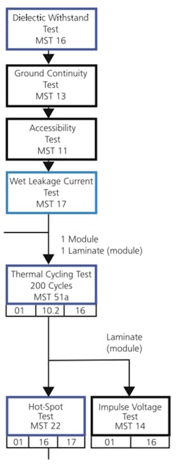
Before the impulse voltage test can be discussed in detail, the testing leading up to it must be addressed. Figure 1 illustrates the electrical shock hazard tests, one of the four groups of tests conducted on each panel. Labs have integrated the tests of two standards—IEC 61646 performance and IEC 6173 safety—in practice.
Figure 1. Electrical Shock Hazard Tests for PV Panels
Electrical Shock Hazard Tests
The electrical shock hazard tests will differ depending on the application class of the module being tested. To correctly forecast the test program for the module, the application class must be determined:
•?Application Class A: for modules operating at greater than 50 VDC or 240 W and in an area where the module can be contacted by the public. This PV panel class has the most stringent testing program.
•?Application Class B: for modules installed in locations not accessible by the public. It has a slightly less stringent test program than the Class A modules, but the differences in testing programs are not significant.
•?Application Class C: for modules operating at less than 50 VDC and 240 W. These less powerful PV panels have a significantly reduced test program.
Electrical shock hazard tests are conducted on three or four of the samples, one of which is the laminate if submitted. First, the batch is subjected to a visual inspection and a performance test. After these tests, the electrical shock hazard test program begins.
All four modules are subjected to the following tests in this order:
1.?Dielectric Withstand Test—conducted at a) 2,000 VDC + four times maximum system voltage for Application Class A, b) 1,000 VDC + two times maximum system voltage for Application Class B, and c) no test for Application Class C.
The dielectric test is conducted twice, once at the voltage noted for one minute and once at 500 V or the maximum system voltage if greater for two minutes. For passage, there cannot be any evidence of arcing or tracking, and the module must pass an insulation resistance test at the conclusion of the dielectric withstand test.
2.?Ground Continuity Test—conducted on all modules. A low-voltage high current is applied to the circuit between the grounding point and the point on the frame farthest away. This connection cannot have more than a 0.1-? resistance value after a two-minute test. The value of the constant current is 2.5 times the recommended maximum fuse rating for the module.
For example, if the maximum overcurrent protection specified by the manufacturer for the module is 15 A, then the ground continuity test would apply 37.5 A between the ground lead and the frame for two minutes, with a resistance of 0.1 ? or less at the end of the test.
3.?Accessibility Test—conducted only on Application Class A and B modules. A probe is used to ensure that live parts cannot be contacted.
After these four tests are conducted, two of the samples are used for additional electrical tests, and the other two are subjected to the following tests:
4.?Wet Leakage Current Test—conducted only on Application Class A and Class B modules. The module is immersed in water and, while immersed, subjected to an insulation resistance test.
5.?Thermal Cycling Test—where the module is subjected to 200 cycles in a chamber with temperatures between -40°C and +85°C for a minimum of 10 minutes at each extreme per cycle. An insulation resistance test at the conclusion of the cycling must yield the same result as the control (untested) module. The thermal cycling test is conducted on all application classes.
6.?Light Soaking Test—conducted on all PV panels where they are irradiated by natural sunlight or the equivalent until stability is reached. The power output of the panel must be at least 90% of the manufacturer’s claim. After the test, the module must be undamaged and have the same output characteristics as a new panel.
7.?Dielectric Withstand Test—conducted a second time on modules or laminates in Accessibility Classes A and B.
Impulse Voltage Test Overview and Methodology
If all these tests are conducted with acceptable results, the final test on this set of modules or laminates is the impulse voltage test. It is performed only on Accessiblity Classes A and B, and the scope of the test differs between the two classes.
Modules submitted for approval for use in installations requiring Accessibility Class A are subjected to higher impulse voltages than Accessibility Class B modules or laminates. The impulse voltage is based on the maximum voltage of the module. For systems with a maximum voltage from 100 V to 150 V, Class A modules will see a 2,500-V peak impulse while Class B modules will see 1,500-V peak.
Wrapping the Sample
To prepare the module for the impulse voltage test, it is completely covered with one or two layers of 0.001-in. or 0.0015-in. thick copper foil so the total buildup is 0.002 in. to 0.003 in. This foil is not available in widths large enough to cover the module, so the pieces are joined together using conductive glue. The standard gives us some guidance on the glue characteristics, specifying “conductivity <1 ?, measuring area: 625 mm2 [1 in.2].”
After the module is successfully wrapped, the negative lead of the impulse voltage tester is connected to the foil, and the positive lead is attached to the shorted output terminals of the module. The impulse tester then is set to deliver a 1.2-µs x 50-µs pulse. The test is repeated three times and then conducted three more times with the polarity reversed. If there is no tracking or breakdown and the module survives a visual inspection, the test is considered passed.
Impulse Voltage Test Equipment Considerations
The impulse voltage test described as MST 14 in IEC 61730-2 is a very specialized test, and as a result, the impulse voltage test equipment needed to conduct it is specialized as well. At first glance, the test specification seems pretty generic. The purpose of the test is to verify that the module will be able to “withstand over-voltages of atmospheric origin”. The test also is performed to ensure that the module can withstand any line-conducted surges.
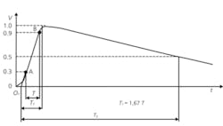
The graph of the voltage surge waveform looks simple enough, a 1.2-µs x 50-µs waveform with the same waveform tolerances as noted in IEC 1180-2. This output is common to most 1.2-µs x 50-µs generators such as those designed to perform insulation tests for IEC 335, for example.
However, impulse voltage generators described in IEC 1180 and IEC 61000-4-5 must deliver in-tolerance waveforms into an open circuit. This is not the same load found when testing PV panels to the requirements of IEC 61730-2. This is because the surge impulse is to be judged while the pulse is being delivered to the panel.
This means that the 1.2-µs x 50-µs pulse is to be delivered with the correct waveform to the panel during the test, and the capacitance of the module itself changes the characteristics of the waveform. That is, the waveform correctly delivered to the panel may not be a correct waveform when delivered into an open circuit.
Almost all surge generators are built to supply a proper voltage waveform into an open circuit. If an impulse tester is designed to meet the requirements given in EN 61000-4-5, it is not able to provide a proper waveform for the PV impulse voltage test because EN 61000-4-5 defines the voltage waveform as delivered into an open circuit.
EN 61000-4-5 Part 1, Scope is written to “establish a common reference for evaluating the immunity of electrical and electronic equipment when subjected to surges. The test method documented in the part of IEC 61000 describes a consistent method to assess the immunity of an equipment or system against a defined phenomenon.”
This standard is referenced in many end-use standards and has been well received. However, there is no requirement that standards writers use EN 61000-4-5 or adhere to all of the requirements.
This note is part of the Scope of EN 61000-4-5: “…this is a basic EMC publication for use by product committees of the IEC. As also stated in Guide 107, the IEC product committees are responsible for determining whether this immunity test standard should be applied or not, and if applied, they are responsible for determining the appropriate test levels and performance criteria.”
In the case of IEC 61730-2, the standards committee may have felt the requirements of EN 61000-4-5 were not adequate for the impulse voltage test. In any event, they have specified a different criterion for waveform delivery which requires specialized test equipment capable of delivering a 1.2-µs x 50-µs voltage waveform into a capacitive load. Although waveform tolerance is not specified, it seems appropriate to use the tolerance requirements given in IEC 1180-2 and IEC 61000-4-5 for this waveform.
Surge test equipment specifically designed to perform the PV panel impulse voltage test is commercially available. This equipment must be designed to store approximately three times the energy required for an EN 61000-4-5 impulse generator, and it must be available with taps corresponding to the capacitance measured in each PV panel prior to testing. These taps must be provided so any capacitance value with that tap’s range will deliver a waveform that is in tolerance according to IEC 1180-2.
Compliance West has found empirically that the power developed by the impulse tester will not improve the waveform above a capacitance measurement of approximately 80 nF. Above that capacitance, real-world considerations of lead impedance prohibit proper waveform generation.
This problem is noted in IEC 1180-1, Paragraph 6.2.2, NOTE: “In specific cases, such as during tests on low impedance objects, e.g. large capacitors, it may be impossible to adjust the shape of the impulse within the tolerances recommended, to keep the oscillations or the overshoot within the specified limits, or to avoid a polarity reversal. Such cases should be dealt with by the relevant technical committee.”
Our tests show that this limit is around 80 nF when testing at 8 kV, the highest voltage level anticipated by EN 61730-2. Therefore, our PV surge generator is calibrated only to that level. Taps are provided above that level, but overshoot is outside the tolerances stated in IEC 1180-2 so no calibration is possible for those taps.
Special Test Considerations
When the impulse voltage test is conducted on PV modules, the technician must measure the capacitance of each panel being tested and use the proper tap on the surge generator to make sure that the pulse delivered to the panel is in tolerance. If the capacitance of the panel is >80 nF, it appears that proper pulse delivery is problematic.
We believe this is a problem whose solution may require extremely expensive means to lower the impedance within the tester. Although pulse delivery above this level is not correct because of overshoot, we believe the cost benefit ratio leans toward conducting the tests with the anomalies.
We further recommend that an accurate high-voltage probe be used to monitor the waveform as delivered to the panel to ensure that it is correct with respect to peak voltage and waveform shape. The waveform should be in tolerance with IEC 1180-2, as shown in Figure 2. We have found that the Tektronix P6015 Probe gives excellent results.
Figure 2. Impulse Voltage Test Waveform
Summary
IEC 61730-2 controls the testing procedure required for PV modules. The impulse voltage test is part of this procedure, and it is conducted as one of the last tests in the test matrix. The requirements are nonstandard and require special equipment and careful testing practices to conduct correctly.
About the Author
Jeffrey D. Lind is president of Compliance West. He began his career in the electrical product safety industry working at Underwriters Laboratories from 1976-1982, then lent his skills to Atari™ as a product safety engineer for a year, and in 1983 worked with Sega Gremlin™ before launching Compliance West. Mr. Lind received a B.S.E.E. from Cal Poly San Luis Obispo in 1976. Compliance West, 2120 Jimmy Durante Blvd., #118, Del Mar, CA 92014, 858-481-6454, e-mail: [email protected]


