Without question, a thunderstorm is very dangerous. It can produce high winds, tornados, hail, and floods, which usually are not big problems for boats or ships. But it also creates ESD events called lightning. And, lightning discharges can be a serious hazard to a boat’s structure, electrical and electronic equipment, and crew.
Even if the lightning strike does not sink the vessel, a single stroke can critically injure crew members, disable the boat or ship, and destroy all electronics, leaving the vessel stranded with a life-threatening emergency and no means of communications. More people are killed each year by lightning than by any other weather-related phenomena. And when far from shore, there is no safe haven.
NFPA-780: Standard for Installation of Lightning Protection Systems calculations indicate that a boat with a 50-ft mast is likely to be struck one time in an 11.2-year period. This may not be a frequent occurrence, but lightning protection needs to be addressed just in case.
It is not completely understood how the charge separation that produces lightning occurs, but a thunder cloud behaves like an ESD generator. Electrostatic potential within the cloud, between two clouds, or between the cloud and earth continues to increase until the dielectric breakdown potential of the air, approximately 1 to 3 MV/m, is reached. Then lightning can occur, and leaders are formed. Because like charges repel each other, a positively charged region like a charge shadow exists under the cloud at the earth’s surface and in those objects mounted or standing on it. This charge shadow follows along under the cloud as it moves.
There are two forms of lightning: positive and negative. The polarity depends on the region of the cloud where the arc originates. Of the strikes, 95% are negative with the average peak current for the first strike being approximately 20 kA to 30 kA and accompanied with ongoing restrikes at about half that value. Unfortunately, the ongoing restrikes have much faster rise times which increase the inductance problems and bandwidth. Less than 1% exceeds 200 kA which generally is used for design calculations. The magnitude of the charge is determined by the size of the cloud. Big clouds produce big charges.
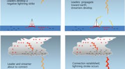
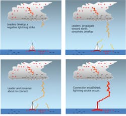
Figure 1. Development of a Lightning Strike
When a negative leader reaches close to earth, certainly within striking distance which is about 100 ft and the radius of the rolling ball, the high negative charge density at the leader tip begins to repel electrons from the sharp points and edges of all positively charged conductors and nearby air molecules. This occurs as a result of a sharp change in surface curvature combined with a reduction in the separation distance between the leader and earth. Mostly, an object higher than its surroundings, such as a mountain, hill, radio tower, church steeple, tree, person, or boat mast located within or along the edge of the charge shadow region, is targeted.
The high electric field (EF) creates multiple positive-charged ion streamers throughout the strike zone that stretch toward the tip of the leader. The lightning discharge path and what gets struck is determined by the first upward streamer that connects with the downward leader (Figure 1). This characteristic makes shipboard-mounted antennas and sailboats particularly vulnerable to being struck by lightning.
Sailboats are struck approximately 25 times more frequently than power boats. When the connection is made, the leader is grounded through a low-impedance path formed by a filament of electrons and ionized air molecules stretching from the earth to the cloud. At this point, a lightning event changes abruptly from developing a high electrostatic potential voltage to creating a high current magnetic field. This is just like any other ESD event only much larger in magnitude.
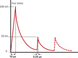
Figure 2. Simplified First and Restrike Waveforms
A simplified lightning current waveform from IEC 62305-1: 2006 Protection Against Lightning—Part 1: General Principles illustrates the lightning threat (Figure 2). Refer to Reference 1 for a more in-depth description of a lightning waveform.
Behavior of the Lightning Protection System
A lightning protection system (LPS) is not a lightning prevention system, and it does not attract lightning. It is designed to be a designated intentional low-impedance path for the lightning current to take to earth should a lightning leader come within striking distance of the LPS. It usually will divert lightning away from objects that are completely contained within the zone of protection and protect them from a direct strike if they are not within the flashover region.
An LPS is a bonding, grounding, and shielding configuration made of four distinct parts: air terminals, down conductors, a low-impedance ground system, and flashover protection.
Air Terminals
Air terminals are designed to be the preferential lightning strike attachment location. These can be single rods, dissipation elements, or overhead wires. The air terminal launches the streamer. The single pointed rod has been doing this since about 1750 when Benjamin Franklin invented it so it is definitely a proven technique.
Dissipation elements are new and work quite well as air terminals. They may even be better at streamer initiation than a single rod. Air terminals define the LPS protection zone and generally are located on the mast a minimum of 10 inches above any protected structure or hardware.
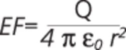
The air terminal height is important because charge (Q) concentrates at high points relative to the surroundings. The associated EF is described by
As indicated by the distance squared term, a small difference in height makes a large difference in the EF. Because height places the more intense EF at points closer to the leader, the higher, more pointed objects create streamers before lower, flatter objects will.
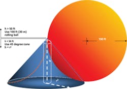
If the air terminal is a single rod or dissipation element, the protection zone will be a flared trumpet-shaped cone formed by a 100-ft radius sphere. It can be approximated with a straight-sided cone with angle a. For an overhead wire, the zone will be a wedge with cone-shaped ends.
Additionally, the larger the leader charge, the larger the angle a and the larger the final jump distance. This means that low-magnitude strokes must be closer to a vessel to be captured by the LPS.
In the United States, the design angle a varies from 30 degrees to 63 degrees depending on the desired probability of lightning capture. Typically, a 45-degree cone is used for mast heights up to about 50 ft, after which the 100-ft radius rolling ball, representing the last jump strike radius and risk, is used. If the vessel is heeled, the mast tip and air terminal move over the side, and the protection cone moves with it. Depending on the mast height and heel angle, the bow, stern, and windward side may no longer be protected.
Figure 3. Lighting-Protected Volume Showing Cone vs. Rolling Ball
Down Conductor
The down conductor interconnects the air and earth terminals and provides a preferential low-impedance lightning path to earth away from crew, components, systems, and materials that might be injured or damaged. If the conductivity and cross-sectional area of the down conductor and terminal bonding are adequate to handle the short duration currents, the LPS will not be a thermal hazard.
Although the LPS functions within the zone of protection, the down conductor separation should be approximately 2 m (7 ft) from anything else that needs protection from flashover (Figure 3). This is easy to do on an aircraft carrier but impossible on a 10-m x 3-m fiberglass sloop. The 2-m spacing stems from the inductive reactance of the down conductor and the earth terminal resistance, especially for fresh water.
The full return stroke and restrike lightning currents flow through the air terminal and down conductor, and they must be sized to handle the lightning current without melting. This may appear impossible, but the lightning duration time is so short that an AWG#4 (21-mm2) copper conductor or equivalent adequately bonded to both the air and earth terminals is capable of handling the current.
Metal may get hot, but it will not explode like a composite or nonconductor. If the mast is nonconductive, such as composite or wood, then a separate metallic conductor must be run up to the air terminal. If the mast is aluminum, then it is used as the down conductor. See NFPA-780.
The voltage across the impedance of an LPS conductor has an inductance and a resistance value plus an earth terminal resistance value. These are related to the material, cross-sectional area, and length. The path voltage is given by
where:
L = inductance, approximately 1.2 µH/m length
Rd = resistance; R value for AWG#4 copper wire approximately 0.00025 ?/ft. Generally, an aluminum mast and boom will have a resistance less than a copper wire.
RE = resistance of the earth terminal; 0.16 ? for sea water, 640 ? for fresh water
Bad = BdE = 10 m?; resistance values calculated from the equation for a single rod which are readily achievable with a good clamped metal-to-metal connection
i = lightning current from IEC 62305-1: 2006; 200 kA x 10 x 360 µs design first strike lightning current. This is the 1% value; 50 kA x 0.25 x 100 µs restrike current which can occur up to 20 times.
Calculating the voltage with respect to sea water ground at the top of a keel-grounded 15-m (50-ft) aluminum mast
Ungrounded conductors connected to the top of the mast are at these voltages regardless of their orientation unless they are arcing to some nearby grounded conductor. As a result, the voltage of the shrouds and stays at deck level is 398,500 V during the first strike and 3,609,625 V during the restrike.
If there are grounded conductors within the sideflash distance of 1.2 m (4 ft), arc-over may occur. It is necessary to bond these conductors together to equalize the voltage. This is done using a loop/ring conductor around the perimeter of the boat outboard of the crew areas and is extremely important. Refer to NFPA-780 paragraph 10.4.3.
Although not an intentional bonding, an aluminum boom metallically connected through a gooseneck to the mast will be at the mast potential that exists at the location of the gooseneck. If the path from the gooseneck to the earth terminal is 3 m (10 ft), the boom voltage during a restrike is 729,125 V. This has an arc-over distance of 0.24 m (10 in.).
Don’t get close to the down conductor (mast)! Don’t get close to the boom! Don’t get close to the shrouds/stays/chainplates! Go below decks!
Part 2
Part 2 of this article, which will appear in the May issue of EE, continues to explore the LPS configuration with in-depth coverage on the low-impedance ground system and flashover protection. It also will focus on shielding requirements for isolating lightning energy from components and materials that may be damaged by sideflashes plus important considerations regarding the use of highly corrosive materials, grounding procedures, and gas gaps and lightning/surge protection devices.
Reference
1. Brewer, R., “Evaluating Lightning Susceptibility,” EE-Evaluation Engineering, July 2008, pp. 64-70.
About the Author
Ron Brewer is a senior EMC/RF engineering analyst with Analex at the NASA Kennedy Space Center. The NARTE-certified EMC/ESD engineer has worked full-time in the EMC field for more than 30 years and was named Distinguished Lecturer by the IEEE EMC Society. Mr. Brewer completed undergraduate and graduate work in engineering science and physics at the University of Michigan. e-mail: [email protected]
