Semiconductor testing is complex, so it’s not surprising that the leading ATE companies have chosen disparate approaches to reducing cost. Each manufacturer has its own group of customers with specific needs, and the latest ATE technologies have been developed in response to them.
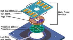
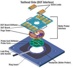
Large, general-purpose testers traditionally have defined electrical and mechanical interfaces that separate the parts of the system associated with the tester from those related to the DUTs being tested. The probe card comprises the actual probe assembly and its connections to the pogo tower. The pogo pins are arranged in predefined positions in concentric rings around the periphery of the probe card and carry the DUT signals upward to the tester’s DUT board.
Figure 1. Traditional Tester Interface With Pogo Tower
Courtesy of Verigy
The DUT board has a pogo-pin contact layout identical to that on the probe card and serves to connect the probe signals to the appropriate test head instrument pins. The DUT board also may contain additional circuitry specific to the DUT being tested, for example, to accomplish signal conditioning ahead of a test instrument input. The physical arrangement of the various parts is shown in Figure 1.
Just as tester manufacturers have defined an interface to the probe card, so too, wafer prober companies have specified the interface between the probe card and the prober. This is only a mechanical specification, but a very precise one. Solving the overall probing problem involves accurate simultaneous X, Y, and Z positioning of perhaps thousands of microscopic contacts. Reliable connections must be maintained in spite of the distortion caused by the hundreds of pounds of force exerted during probing.
Streamlined Prober Interface
Verigy’s V93000 Direct-Probe™ Tester streamlines the prober-to-tester interface by merging the functions of the DUT board and probe card while totally eliminating the pogo assembly. You may well ask why such a radical redesign was needed. According to the company, signal integrity has become a big problem because of the high level of integration in today’s chips.
Rather than qualifying a chip at wafer test to be bad or probably good, a more complete functional test now is required. This is especially true when large chips are stacked in a multidie package for very compact phones and cameras. Known good die (KGD) must be provided for these systems-in-packages (SIPs) to ensure high yield at final test.
Verigy claims that pogo tower-based wafer prober interfaces degrade signal quality because the signal must travel 4 to 5 inches and pass through multiple transition points. The Direct-Probe solution places the test head down into the prober and interfaces directly with the probe card, achieving higher quality signals.
According to Hans-Juergen Wagner, Verigy’s vice president of SOC test solutions, testing currently done with handlers on singulated packaged devices is moving to multisite, nonsingulated testing on wafer probers. This means that device packaging is becoming the last step in wafer processing, driving final testing onto the probe line.
Increased Integration
Rather than changing the tester-to-DUT interface, Teradyne has concentrated on improving test instrument capabilities. According to Rod Stewart, general manager of the SOC business group, “The combination of increased integration with higher site count and implementation of concurrent test has driven the need for ATE to provide instrument boards that can support an increased number of channels per board, microwave instruments to support many more RF ports per device, software to support the rapid implementation of concurrent test, and system architecture that supports multiple time domains and background DSP to address multisite and concurrent test requirements.”
More Channels
As described in the datasheet for Teradyne’s UltraPin800 high-density UltraFLEX™ digital instrument, four data types are provided: digital pattern data predetermined from design tools or created by the test engineer to generate and analyze logical data sequences using large vector data memory, digital signal data for digital representations of analog waveforms using dedicated source and capture memories, SCAN data with long serial bit streams for DFT applications, and memory pattern data algorithmically generated by hardware in real time to test embedded memory.
The UltraPin800 has 128 single-ended pins or 64 differential pin pairs. Each pin includes a parametric measurement unit that can force voltage from -1 V to +6 V at currents from -50 mA to +50 mA. The pin termination is selectable as a high-impedance, 50-?, or an active current load.
More RF Ports
With the UltraWave 12G wireless test instrument, UltraFLEX users can address a range of RF device testing up to 12 GHz. The instrument really is a configurable RF test system that provides up to 64 universal test ports. In an example configuration, the 12G occupies three instrument slots and supports 16 universal ports, eight DUT reference sources, and four independent synthesizers.
Architecture
According to Mr. Stewart, “Teradyne’s approach is to create platforms that we can refresh over time with new instruments to give more capability to our customers.” Clearly, the 12G and UltraPin800 instruments fit that description. In addition, the tester architecture must be capable of supporting various test strategies.
In the UltraFLEX, a series of dedicated buses and DSP engines operates in the background to ensure optimum throughput for multisite, concurrent test programs. This kind of testing generates lots of data quickly, and the background DSP system eliminates the overhead associated with moving data and processing the results.
Another feature of the UltraFLEX architecture is the Sync-Link™ capability that supports multiple timing domain testing. Effectively, Sync-Link provides a dedicated test controller per time domain and allows the test programmer to assign instruments to specific time domains.
Of course, you may not need quite as sophisticated and versatile a solution as one based on UltraFLEX, in which case Teradyne testers, from what were previously the Nextest and Eagle Test product lines, might be suitable. Matching the right tester to the application is yet another way to reduce the cost of test.
Redistributing Test
The Cassini tester from Roos Instruments takes a much different approach from that used by many manufacturers. Instead of emphasizing core capabilities, Cassini delegates almost all test-specific details to particular test instrument modules (TIM). Three versions of the base unit support either eight or 16 TIMs with up to three infrastructure sources.
According to CEO Catherine Rossi-Roos, “The company has responded to a significant increase in high-mix, low-volume applications by introducing multiple TIMs. These include a 120-pin high-speed digital module that the tester self-configures as a protocol-aware solution for JTAG, BIST, vector, or signal-based digital I/O. A single tester can support more than 1,000 pins of these types of digital I/O.
“For baseband,” she continued, “the RF pin TIM uses a unique FPGA-based approach combined with digital up-conversion to provide source and measurement of complex wireless LAN, WiMAX, and cellphone digital modulation capability. We also have developed mmWave solutions for applications to 80 GHz and are testing in-package on a handler up to 40 GHz. In addition, a special version of Cassini offers almost unlimited RF ports to 12 GHz.”
Ganging Up
LTX-Credence’s cost-reduction efforts have been strengthened with the introduction of the integrated multisystem architecture (IMA). All future products will be developed around the IMA, and the first implementation is available now for the Diamond tester. Steve Wigley, vice president of marketing, elaborated, “IMA enables 10-slot Diamond Test Systems to be ganged together for massive multisite testing of microcontrollers.” In addition, the testers still can be used separately should test requirements change.
Accurate Analog Test
Analog and mixed-signal test now can benefit from a new LTX-Credence data converter test module with eight independent sources and eight independent measurement channels. Resources are arranged as four groups of two sources and two measurement channels, each group supporting 24-bit source generation and 18-bit DUT output measurement. Also, one source in a resource group can be used to null the output of the DUT driven by the other source, the resultant being amplified by up to 200x for very high-resolution analysis.
Multifunctional Modules
As explained by Mani Balaraman, director of SOC product engineering at Advantest, offering multifunction instruments that provide analog, digital, and power functionality per tester pin avoids the need to switch among multiple instruments on the load board. The load board becomes less crowded and more reliable as well as easier to design.
The company’s T2000 Integrated Power Test Solution (IPS) is an example of this technology that features Kelvin force/sense capability, signal line guarding, and high stability. Because the sets of resources demanded by parametric tests on complex devices reside in one instrument, correlation of test results is faster. All these factors improve the cost of test.
New Technologies
Separately, Advantest has developed a functional test abstraction class of test methods to support a number of protocols such as JTAG, SIP, HDMI, and PCIe. In this new test development and debug use model, the engineer can stimulate and analyze the DUT in its native mission mode, which should reduce the time required to get new silicon up and running.
The company also is developing tools to address high-speed serial protocol testing. Traditional ATE functional test methods don’t work well for this application because a DUT may go through an elaborate training sequence with a variable number of device cycles; packet formats may include CRC fields, which makes pattern generation very difficult for a tester; and designing the best set of patterns for functional test is challenging because of the huge number of state transitions a DUT can go through.
Summary
Better matching between the test tool and the test application is the common theme running through new and upgrad-ed ATE capabilities. A thorough review of your current test approach may be a good idea. The improvement made possible by adopting a new solution and the short payback associated with such an investment might surprise you.

