Designers often develop a single board that can be configured using different firmware for multiple end-user applications. This approach allows companies to reuse critical intellectual property and leverage research and development activities for maximum profit and fastest time to market. It also makes it easy for designers to revise product functionality and implement additional capabilities without requiring changes to the physical board in either the initial stages of design or as the product matures.
Creating different functionality from a single board design can be accomplished using programmable logic device (PLD) technologies which have reconfigurable circuits. The functionality of the PLD components depends on the firmware downloaded into the device.
Other board designs with high-level processing capability can have their functions changed by updating the flash memory associated with the on-board processor(s). Flash memory is nonvolatile computer storage that can be electrically erased and reprogrammed many times, and it is commonly used in USB memory devices.
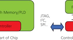
Figure 1. ISP Configurations
Manufacturers have a great deal of flexibility when deciding where and how to program the firmware into the PLD components or data into flash memory. Some products are designed to be reprogrammed in the field and have in-system programming (ISP) capability built right into the board. The ISP can be achieved through an on-board processor, links to serial protocols such as boundary scan, or a mixture of on-board and on-chip capabilities (Figure 1).
Components can be programmed at many stages during the procurement and manufacturing process:
- Prior to PCB assembly by the component vendors.
- By stand-alone PLD programmers at the PCB manufacturing facility or dedicated programming houses.
- By equipment integrated into manufacturing pick-and-place equipment.
- By post-assembly in-circuit test (ICT), functional, or system test equipment.
- Remotely at the end-user’s premises using wireless Ethernet broadcast techniques if the boards have ISP capability.
Pre-Reflow Programming
Today, about 50% of programmable devices are programmed prior to being placed on the board. These tend to be high-volume products whose functionality does not need to change after the design is finalized.
Pre-Assembly Programming
Programming prior to assembly normally offers the most cost-effective method and separates the programming time from the beat rate of the manufacturing line. Long programming times can negatively affect the line beat rate when they are longer than the time it takes at any other stage in the manufacturing process.
Devices programmed before the assembly process can be cost prohibitive. Changes required to the PLD firmware after the devices have been programmed can be costly and add time delays to manufacturing because stock must be replaced or reprogrammed.
Normally, preprogrammed devices cannot have board-specific information in them before being placed on the board. As a result, an additional stage will be required to add information such as serial numbers or MAC addresses used for Ethernet-enabled products.
Programming in the Placement Machine
Programming blank devices in the feeders of chip placement machines allows for the firmware content to be programmed immediately before the PLDs are placed on the boards. With this process, data can be changed and custom information added, such as serial number and MAC address.
The limitations of this approach are cost, programming time, and reliability of the process. Most programmable devices are fine-pitch or BGAs that are removed from a reel and placed into a socket for programming before being passed to the placement machine. Socket reliability and potential damage to the leads/balls of the device to be placed are concerns. High-cost, high-reliability sockets must be used and maintained on a regular basis to prevent damage to the devices. To overcome programming time issues, the placement-machine programmers can be configured to accommodate multiple PLDs at the same time to keep up with the manufacturing beat rate.
Post-Reflow Programming
If 50% of devices are programmed before reflow, then the remaining 50% are programmed after reflow. This percentage is likely to change over the next few years as new phase-change memory (PCM) technologies become more popular.
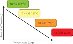
Figure 2. Data Retention at Temperature for PCM Devices
As long ago as 1968, it was noted that certain glasses exhibited a reversible change in resistivity upon a change in phase. In 2003, Intel, Ovonyx, and STMicroelectronics joined forces to accelerate progress on this technology.
PCM and similar nonvolatile memories are faster and denser and have a longer life than current technologies. However, they are temperature sensitive so data can be lost during the reflow stage of manufacturing (Figure 2). The data in PCM components will be erased and revert to all 1s if they are exposed to temperatures greater than 225°C for more than 10 µs. Even at lower temperatures like165°C, data in these devices is lost within 10 s. Normal reflow temperatures are around 210°C to 235°C which means that all PCM type devices must be programmed after reflow at purpose-built programmers, ICT, or functional or system test.
Purpose-Built Programmers
Purpose-built programmers typically add another stage to the manufacturing process and can be located before or after any electrical inspection stage. Programming before electrical test allows the electrical test stage to verify that the devices have been programmed correctly.
Purpose-built units normally need the board to be designed for ISP and will use a Joint Test Action Group (JTAG) IEEE 1149.1 Standard controller that connects to the PCB via a cable to program the devices. If the board is not designed for ISP, then the programming systems must emulate the pre-assembly programmers and be interfaced to the board with a connector or bed-of-nails interface.
These types of programming units must be designed and integrated into the line. They often are unique to the board design, which can add cost to the manufacturing process, slow the line beat rate for large devices, and take up valuable manufacturing floor space.
In-Circuit Test
ICT is an ideal stage for programming devices because it doesn’t matter whether or not the board is designed for ISP. Access afforded by the ICT bed-of-nails interface for testing allows the device to be programmed using any of the serial communications protocols and the existing tester digital hardware. The ICT system must provide the correct voltage levels and verify that the levels are within the electrical specification of the device manufacturers.
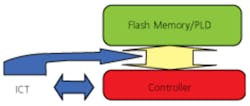
Figure 3. ICT Programming Devices
Some serial communications protocols use logic families as low as 400 mV with just 100-mV separation between high and low logic values. To be effective, the ICT system must source and measure digital signals down to these logic levels safely and accurately.
The bed of nails allows direct access to program the device as it would be in the device programmer (Figure 3). Any noise issues associated with the ICT fixture due to the interconnects can easily be dealt with using dual-height fixtures where necessary and ensuring that interconnected devices are properly isolated using inhibit and disable software techniques. These techniques give the ICT system the capability to control interconnected devices so they do not interfere with the ISP programming routine.
ICT systems also have backdriving capability that can be used to force device pins to the desired logic states regardless of the on-board value. To prevent electrical overstress due to backdriving during the lengthy ISP programming times, use an ICT system that has backdrive current monitoring and control features that help eliminate and reduce potentially harmful backdrive currents and overvoltage conditions.
The latest ICT systems can provide gigabytes of data to the PLD while driving the control signals at speeds that allow the data to be programmed as fast as stand-alone programmers. Some ICT systems store the programming data in dedicated controller memory to reduce load times and enable changing of the firmware data on the fly without having to change the ICT program.
Even though there are many benefits to performing ISP at ICT, some devices are very large and may take so long to program that manufacturers prefer not to tie up ICT systems performing lengthy PLD programming routines. In these situations, manufacturers may program devices prior to ICT using a simple programmer and then customize the data later at ICT with board-unique information such as serial number, MAC address, and board manufacturing history.
The latest ICT systems should not be confused with manufacturing defect analysis (MDA) test systems or older ICT systems. These less capable systems do not have the digital test capability or could damage expensive programmable devices by exposing them to inaccurate voltages and currents. They also rely on additional equipment to program devices after the tests have been completed.
The MDA just provides power to the board and some simple control of the programming module. But because the programming module normally is external to the system, it adds cost to the process. It’s quite common that low-cost programmers must be changed as the device type changes and consequently can be board specific.
Functional or System Test
Functional and system test are both additional locations in the production line that can program devices as long as the board has been designed to allow it. Generally, boards designed with ISP are not a problem, but other boards may require some additional access. Unlike ICT, they may not have the full access allowed by the bed-of-nail interface or the sophisticated digital drivers/sensors that allow the ICT system to overdrive logic levels to condition the board for programming. Otherwise, these electrical test systems should perform in a similar way to the ICT system.
Boards designed for ISP are easier to program and normally can be controlled by the test system. If the board has intelligent processors, then the test system can just provide power and simple commands to the PCB that instruct the processor to program the board firmware. These boards will link either by hardwire connections or wirelessly to the source data, download, and then program the ISP device.
Again, the limitations may be programming time and the necessity for multiple stations. This can be especially true if the device can only be accessed using software drives such as a USB drive in a Windows or UNIX environment where overhead can have a dramatic effect in slowing down programming times.
Summary
With the introduction of technologies such as PCM and the potential loss of data during the reflow process of manufacture, programming will have to migrate from pre-reflow to post-reflow. The functional and system test stages can be used to program devices, but they may not always have the resource needed to perform the process.
Historically, ICT has been an ideal place in the production line to program devices. This is because of the capability of the digital test subsystem, access through bed-of-nails interfaces to program boards designed with or without ISP capability, and elimination of any incremental cost in equipment if the system can provide controlled, safe electrical logic signals. When loading large amounts of data that may exceed the line beat rate, a simple dedicated programmer can be used after reflow to add customized data.
About the Author
Michael J. Smith has more than 30 years experience in the automatic test and inspection equipment industry with Marconi, GenRad, and Teradyne. He has authored numerous papers and articles and chaired iNEMI’s Test and Inspection Roadmaping Group for many years. Mr. Smith received a BSc(Hons) in control engineering from Leicester University and is a member of the Institution of Engineering and Technology. [email protected].
The author would like to acknowledge Alan Albee, the in-circuit test product manager at Teradyne’s System Test Group, for his contributions to this article. Teradyne, 700 Riverpark Dr., MS-NR-7001-1, North Reading, MA 01864, 978-370-6238, [email protected]


