The most flexible way to connect signals and instruments is to use a switching matrix. In a test application, there often are many more signals than measuring instruments, necessitating signal switching. Nevertheless, although a matrix is the most general solution, it may not be the best one.
If all the signals were at low frequencies or DC, at least a few volts in amplitude, and from low-impedance sources, the exact nature of the switching system would be relatively unimportant. However, even for such well-behaved signals, there are limits to what is practical.
Nick Turner, president of Cytec, commented on size limitations for matrices and multiplexers. He said that if a signal connects to a large number of relay contacts in parallel, as it would in a big matrix, the overall capacitance of the contacts limits high-frequency performance. If, instead, switches are arranged in a tree structure, capacitance is reduced but the number of series connections adds resistance that can be a limiting factor. At low frequencies, a matrix can be very big, the number of relays being the main concern.
Cytec’s MESA Series Controllers support construction of large switching systems having matrices, multiplexers, and individual relays depending on what best fits the application. Low-level, RF, audio, video, high-voltage, or high-current signals are accommodated by a range of expansion chassis types. Some of these, such as the DX/256×256 Digital Matrix, use high-density solid-state switching.
The theoretical background for large matrix design stems from work done decades ago on telephone switching systems. Faced with the need to provide sufficient circuits to ensure good customer service but also with the impracticality of supporting huge switch matrices, Charles Clos and others at Bell Labs devised a range of alternative matrix structures.
A square matrix is one with N inputs and N outputs and requires N2 relays. Although for some applications using 10,000 relays to construct a 100×100 matrix might be practical, it is obvious that for many it is not. Clos analyzed 3-, 5-, and 7-level switching systems to find implementations with a minimum number of relays while still providing performance equivalent to that of a square matrix. A matrix that allows all N inputs to be connected to N outputs is called nonblocking. In telephone terminology, none of the N callers wanting to be connected to the N parties they had called would get a busy signal.
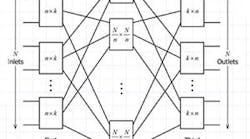
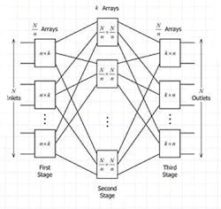
To switch 36 inputs to 36 outputs, Clos found that a 3-level circuit only required 1,188 relays instead of the 1,296 needed to build a square matrix. His 3-level circuit assigned inputs to six 6×11 submatrices. The middle section has 11 6×6 matrices, and the output section is just the inverse of the input with six 11×6 matrices. In total, 6×66 + 11×36 + 6×66 = 1,188. The advantage of a 3-level circuit increases with size, requiring only 5,700 relays to build a 100×100 matrix (Figure 1).
Courtesy of Assumption University Thailand, Telecommunications and Electronic Engineering Curriculum Course TE4107 Digital Switching
Assigning the input submatrix size as the square root of N is a good starting point but does not necessarily result in the absolute minimum number of relays. Clos’ analysis of multilevel nonblocking matrices was extensive, but the more important point he made was that blocking matrices can afford even higher savings while keeping subscribers relatively happy. Very large (blocking) telephone exchanges are practical because of A. K. Erlang’s statistical analysis of call traffic in the early 1900s.
For a 1,000-circuit nonblocking matrix, a 3-level approach requires 186,737 relays, and a 5-level design needs 146,300. In contrast, a 1,000-circuit blocking matrix with 708-erlang capacity can be constructed using only 79,900 relays. An erlang is a unit of telephone traffic loading, typically equivalent to one caller talking for an hour. If an average call lasts for less time, more subscribers can be accommodated. A blocking matrix is called a sparse matrix if only a few paths are provided between the inputs and outputs.
Test System Matrices
The basic telephone switching systems Clos designed only connected a caller to one other subscriber. Usually, that is the intended operation of a switch matrix within a test system. Nevertheless, it is possible in a nonblocking matrix to make many column connections to a single row or from a column to many rows. Controlling the application of power to several DUTs could be a good reason to do this. You also might want to connect the same input signal to multiple DUTs, but in this case, loading could become a problem even if the signal frequency is low enough that reflections are not.
Pickering Interfaces’ business development manager David Owen explained that “[nonblocking] matrices may allow more than two points to be connected together simultaneously, but that always introduces a bandwidth and crosspoint degradation because the matrix loading will be higher and the system is less likely to be a uniform RF design.” Indeed, the general goal is to connect one output to only one input, and the matrix control software provided by many companies is based on this premise.
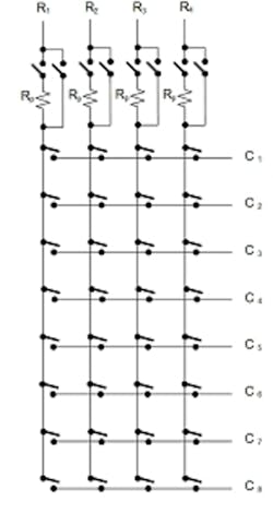
Alan Lesko, application engineer for software and modular solutions at Agilent Technologies, commented on the need for resistance in series with each row. “The life of the relay can be extended by reducing surge currents that may occur during switching. A common technique to improve relay life is to add about 100 Ω of resistance into the path. This method works well when making measurements through the matrix. However at times it is essential to source currents through the matrix, and in this case, the protection resistors will interfere with current flow,” he explained.
According to Lesko, the unique topology of Agilent’s 34934A Matrix Module provides a solution for this situation. The resistor bypass switches, he said, create a path around the protection resistors when currents need to be sourced through the matrix (Figure 2).
Expansion
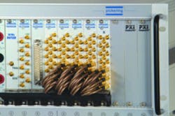
Pickering’s Owen said, “The simplest method of expansion in PXI usually is to define the required Y-axis size and then deploy multiple modules with their Y-axis connections linked together. This increases capacitive loading and lowers bandwidth both because of the matrix capacitance and the cabling capacitance,” he explained. “Even so, some modules, such as the 40-726A—a 12×8 RF matrix, do provide loop-thru connections to allow expansion while minimizing the impact on bandwidth” (Figure 3).
Courtesy of Pickering Interfaces
Bob Stasonis, the company’s sales and marketing director, cautioned that expansion has practical limits. “Once the expansion requires a significant proportion of a PXI chassis, for example, we recommend that users consider a nonmodular LXI-based solution. It usually will perform better, be less expensive, and occupy less test space because of the mechanical freedom,” he said.
LXI often is a better format for large matrices. Besides allowing more relays to be housed in a single chassis, the greater panel area accommodates more design options. For example, readily available D-sub connectors might be chosen instead of a less common, physically smaller type with higher contact density.
Precision Filter’s Doug Firth, vice president of business development and engineering, described the company’s 464kB Solid-State Switching System. “[This] is a 3-stage switch matrix with a modular-based construction using plug-in cards. The system uses solid-state CMOS technology and contains buffers for all switch I/O to maintain a 1-MHz signal bandwidth independent of switch-system size. Users can purchase matrix sizes between 96×96 and 512×512,” he said.
“One 464kB switch system chassis can support up to 256×256, and four chassis can be cabled together to form a switch matrix of 512×512. While switching within one box does not rely on relays, relays are on the outputs along with busing connectors on the inputs and outputs to allow a user to easily build a larger switch matrix,” Firth concluded.
The equivalent terms “analog bus” and “backplane signal raceway” are used by many companies to describe how a matrix may be expanded. The following comments from Charles Greenberg, senior product marketing manager at EADS North America Test and Services, explain in detail how such a bus is used. “The Racal Instruments™ 1450F 8×18 2-wire matrix is an example of the simplest type of matrix expansion,” he said. “It is expanded simply by plugging multiple 1450F cards into the Racal Instruments 1830 Source/Measure Switch chassis and closing relays to connect the matrix to the backplane signal raceway for matrix expansion ranging from 8×18 to 8×162 2-wire connections.
“The 1830’s signal raceway expansion bus supports signals up to 300 volts and employs stub-breakers to achieve signal bandwidths of 50 MHz or higher for the expanded matrix,” Greenberg said. “The 1830 also provides an additional type of matrix expansion: an automatic connection (also via bus relays to the backplane) of the matrix to instruments installed in the 1830 such as a 60-MHz digitizer or waveform generator or a DMM.”
“VTI Instruments’ EX1200-4003 Matrix Card hosts two 4×16 two wire matrices with configuration relays that allow the user to programmatically configure the card into a 4×32 or 8×16 matrix,” explained Will Rigsbee, application engineer at the company. “The internal configuration relays allow the matrix to be dynamically reconfigured across rows or columns as needed to maximize performance and functionality by reducing stub lengths of unused portions of the matrix or increasing overall dimensions of the matrix if the full IO functionality is required.”
According to Rigsbee, matrix specialized mainframes provide for up to 16 expansion lines on the backplane supporting connection and expansion of matrices across multiple cards without external cabling that can add signal noise and cost to the system. For example, a full-rack 1U EX1200 Series mainframe can support a matrix up to 4×192.
Subchassis
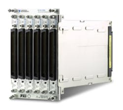
In addition to the LXI and large switch matrices available from vendors such as Pickering Interfaces, Precision Filters, Universal Switching, and Cytec, a number of companies have developed subchassis-based switching systems that are housed in a standard VXI or PXI chassis. National Instruments’ (NI) SwitchBlock (Figure 4) is an example that fits six matrix PCB modules into the space of four PXI slots. Also, special expansion bridges can connect multiple six-module blocks.
Courtesy of National Instruments
Rows on the separate modules connect via a backplane analog bus that in a larger matrix is carried from block to block by the expansion bridges. For any contact closure pattern, at most two PCB modules are required to connect any two columns through a single row. The same relays that connect each module’s rows to the analog bus also can separate unused module rows from it.
As NI’s Jake Harnack, switches product manager, pointed out, this capability is important. “NI SwitchBlock uses isolation relays and intelligent routing algorithms that allow two columns on opposite sides of a matrix to be connected through a minimal amount of relay closures and minimal path length to reduce unwanted capacitance and optimize signal integrity.” Agilent’s Lesko also emphasized the usefulness of disconnect relays in reducing capacitive loading in large matrices.
Pickering Interfaces’ BRIC and Giga-tronics’ (Ascor) 4000 Series are, respectively, PXI and VXI subchassis switching systems. Keithley, VTI Instruments, EADS North America Test and Services (1830), and Agilent Technologies (34980A) offer proprietary systems in which switching and a DMM share a chassis. Proprietary systems may have an initial cost or performance advantage, but repurposing the hardware for a new project can be restricted by a limited choice of function modules. The availability of a wide range of module types and vendors is an advantage of using the VXI and PXI formats.
The RF/Microwave World
Some RF matrices support making multiple connections, but not directly. To avoid reflections, controlled impedance transmission lines and splitters/combiners are used, and there also may be buffer amplifiers to maintain signal levels. This arrangement quickly becomes a special-purpose switching circuit and is unidirectional if amplification is involved.
In the original telephone sense, blocking referred to a reduction in the flexibility of a matrix so that each input could not be simultaneously connected to the desired output. The meaning of blocking and nonblocking has been extended by some RF/microwave matrix vendors depending on the markets they serve.
A JFW Industries application note describes a blocking RF matrix as one in which “Each input signal can be switched to only one output port at a time.” A nonblocking matrix allows an input to simultaneously connect to more than one output.
Fan-out to multiple outputs from one input is accomplished through power dividers. The input signal is split and the multiple parts connected to output multiplexers. This arrangement suffers from reduced isolation because of the limited isolation in the dividers.
JFW adds separate SPST switches following each input power divider to increase isolation. At each output, another power divider allows multiple inputs to be combined (fan-in). The company calls this architecture a super nonblocking matrix—any inputs can connect to any outputs (plurals intended).
Dow-Key Microwave uses the original telephone system meanings for blocking and nonblocking but adds a nonblocking fan-out category to describe matrices that support connections from one input to multiple outputs. The company also uses the telephone switching term “crossbar” to denote a nonblocking bidirectional matrix such as the new CB-Series. As stated in a Dow-Key matrix switch brochure, “A crossbar system can switch any input signal to any output port such that the path between the I/O ports is unique at any given time.”
Sara Nazemzadeh, applications engineer at Dow-Key Microwave, explained, “A large switch matrix solution with coaxial switches quickly becomes expensive and physically big, but it is best used where the system requirement is for broad frequency band DC up to 18 GHz or higher and when high power signals need to be tested (above 1-W CW). Also, coaxial-based switch systems provide better insertion loss, VSWR, and isolation specifications.”
She continued, “Solid-state matrices have a faster switching time and are considered to have infinite life. However, their power-handling capacity is below 1-W CW. Solid-state supports large configurations as well but with limited frequency band due to its nonlinear characteristics.”
Advanced Media Technologies (AMT) describes the company’s Quintech brand SRM-Series RF Matrix Switches with similar full fan-out nonblocking terminology. A complementary SMC Series of full fan-in nonblocking RF matrices also is available. Both AMT matrix families have 75-Ω controlled impedance paths, do not pass DC, and use solid-state switching. Size ranges from 16×16 to as large as 128×128. Target markets include broadband cable and satellite communications.
Mike Dewey, senior product marketing manager at Geotest-Marvin Test Systems, said that the company focused on multiplexer designs for RF because it was much easier to maintain bandwidth. He added, “And, quite frankly, most RF applications require a multiplexer architecture rather than a matrix.”
NI’s Harnack concurred, citing the tendency of unused portions of an extended matrix to increase the capacitive load and number of RF stubs seen by the transmission lines. He explained, “One way to increase flexibility while maintaining RF performance is to minimize stubs through an innovative multiplexer topology, such as the NI PXI/PXIe-2593 Dual 8×1 50-Ω Multiplexer, which internally routes four multiplexer resources to connect any two points.”
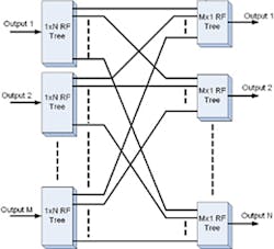
Courtesy of EADS North America Test and Services
The PXI-2593 is an 18-terminal sparse matrix that can be configured in many ways: 2×16, 4×14, and 9×9 are all possible. To achieve so much flexibility, one of the trade-offs is variation in the path length. For example, in a 2×16 configuration, some of the connections are made through four relays and others through seven. Similarly, configured as a quad 3×1 multiplexer, one of the three paths requires four relays while the other two use six. A 500-MHz bandwidth is maintained, but the path length variation could cause subrate jitter in some applications.
Termination also is important in RF/microwave applications, especially for unused inputs. The signals not selected by a multiplexer will be reflected from an open circuit unless a termination is provided locally for each. It is assumed that the selected input will be terminated by the load the multiplexer is driving. Double-throw relays allow a terminating resistor to be connected in the off or deselected position.
EADS’ Greenberg discussed the construction of his company’s bidirectional RF matrices, which simply switch but do not combine RF signals. “A true RF MxN matrix consists of a total of M 1xN RF switch trees or microwave switches, either standalone or configured as a tree, interconnected to a total of N 1xM tree-type blocks as shown in Figure 5. As the dimension of M or N is increased, the cost, complexity, size, and insertion loss of the matrix also increase,” he said. Agilent’s Lesko agreed, explaining that the insertion losses of the individual switches are additive.
Greenberg continued, “Expansion of a matrix of fixed dimensions is difficult due to the amount of hard wiring. The scheme typically used for expansion is ‘advanced planning.’ The custom or off-the-shelf switch matrix is configured as a part of the MxN matrix (M-Rexp) x (N-Cexp) where Rexp and Cexp are the amount of expansion available. EADS North America Test and Services often employs this scheme when configuring a Racal Instruments 1257A LXI Switching Matrix that later may need expansion.”
Summary
There is no shortage of switching matrix products, some standalone, some integrated into a more comprehensive measurement system. In all cases, the signal characteristics determine the most appropriate switching. Cost, complexity, and related instrumentation can be considered after the range of choices has been narrowed to only those switch solutions that will maintain signal integrity.
For More Information
Agilent Technologies
Cytec
Dow-Key Microwave
EADS North America Test and Services
Geotest-Marvin Test Systems
National Instruments
Pickering Interfaces
Precision Filter
Universal Switching
VTI Instruments
