EMI Method for Diagnostics in Electrical Apparatus
This article is part of the TechXchange: Delving into EMI, EMC and Noise
Members can download this article in PDF format.
What you'll learn:
- How EMI testing can provide a condition assessment of an entire system.
- A look at EMI receivers.
- How EMI helps with partial-discharge testing.
Electromagnetic-interference (EMI) diagnostics is defined as the precise measurement and analysis of conducted and radiated signals produced by electrical and mechanical defects in high-voltage systems.
The industry faces challenges where too much emphasis is placed on engineers in the field being able to identify key frequencies by eye or knowledge alone. This will limit the ability to automate the process. Automated identification of insulation faults, using EMI methods, are the best solution to monitor electrical equipment. Applying a reliable, non-invasive surveillance technique will provide the best, most accurate test results.
What Do EMI Tests Reveal?
EMI tests can help identify electrical insulation deterioration as well as conductor-related defects in industrial systems. The early detection of faults will significantly help mitigate the need for reactive maintenance and unplanned system downtime, ensuring continuity of supply. The EMI method is a surveillance technique that can assist in identifying insulation degradation and conductor faults, such as partial discharge (PD) and arcing.
Another example would be the uncovering and identifying of a machine’s mechanical problems like bearing rub or even shaft misalignment. EMI frequency scans can be employed to identify the frequencies that are characteristic of fault conditions.
Time-resolved analysis at those frequencies will enable crucial data for the classification of such faults. With the emergence of continuous online monitoring, there will be a greater need to embed more intelligence within the monitoring devices that automatically recognize any developing fault conditions.
An EMI measurement can provide a condition assessment of an entire system. In the case of rotating machines, this includes the isolated phase bus (IPB), along with the generator, exciter, and breakers connected to it. The measurement can be performed in one of two ways:
- Frequency domain using the EMI spectrum or signature.
- Time domain using the EMI emission at a single frequency.
One of the first successful applications of EMI/radio-interference techniques involved correctly detected conductor deterioration in large, high-voltage generators. A radio-frequency current transformer (RFCT) was initially placed at a generator neutral to collect data. CISPR 16 techniques were later employed by communications engineers to other generator designs, where insulation deterioration was successfully detected.
An EMI Receiver According to CISPR 16-1-1
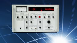
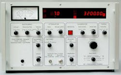
EMI receivers are typically employed to measure unwanted emissions at high frequencies generated by an equipment under test (EUT). These kinds of emissions may be conducted (such as on the power cord) or radiated as an electromagnetic wave. Depending on the type of emission, various coupling devices are available that can pick up the emission and forward it to the receiver (see figure).
Advantages of EMI Diagnostics
One major advantage of this technique is that data can be collected without the need for a power outage. Thousands of successful EMI tests have been performed globally over the past 40 years, with an excellent track record in reliability.
It’s not necessary to install a permanent coupler to collect EMI data. A split-core RFCT can simply be placed around a suitable earth connection. Skilled test engineers can collect all of the required data in about an hour.
EMI Helps with Partial Discharge Testing
When preparing to bring a generator back into service after a rewind, local site engineers are able to perform conventional time-of-flight PD testing. These tests can find such things as increased PD activity on one phase and that the signals may originate from inside the generator—however, the location information was inconclusive. Engineers could then perform additional EMI testing to determine if the PD was genuine, and if so, the source of EMI can be easily located.
Summary
This article presents a level of automation that’s necessary for accurate detection of fault conditions within the EMI frequency scan. We have discussed how a level of intelligence can be embedded within monitoring devices that provide a “diagnostic assistant” capable of identifying the location of insulation degradation faults. This process will help engineers in the field to find the location of possible emerging faults within the system.
Ultimately, a fully automated online condition monitoring process for the surveillance of multiple globally connected assets can evolve—without the need for constant human interaction and decision-making.
Read more articles in the TechXchange: Delving into EMI, EMC and Noise
References
1. The EMI-Receiver according to CISPR 16-1-1.
2. EMI Diagnostics: Isolated Phase Bus.
3. “Automated identification of insulation faults using Electro Magnetic Interference methods,” Electrical Insulation Conference (EIC), Calgary, Alberta, Canada, 16-19 June 2019.

