Many devices today operate at higher voltages, such as silicon-carbide semiconductors, dc distribution systems, electric vehicle batteries, and power subsystems. When devices can source power, they need an electronic load (e-load) to load them down during testing. But as voltages climb to 400 V, 600 V, or even 1000 V, there are fewer e-loads on the market rated for these high voltages. You may consider putting e-loads in series to construct a solution. But most, if not all, e-loads on the market cannot be safely put in series. For those of you wondering why, read on.
How Does An E-load Work?
The most basic e-loads can operate in constant current (CC) or constant voltage (CV). Some e-loads provide constant resistance (CR), constant power (CP), or even constant impedance (CZ), but all of these modes are generally derived from the basic CC or CV function. A CC e-load is used to load down a CV source, such as the output of a dc-dc converter. A CV e-load would be used to load down the output of a CC current source.
Related Articles
- Capacitors Create Challenges When Modulating DC Power
- Do You Have Enough AC For Your DC?
- What Is An Autoranging Power Supply?
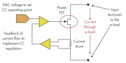
Looking more closely at the CC programmable e-load, the e-load controls the amount of current flowing by adjusting the RDS of the FET (Fig. 1). The series resistor (current shunt) senses the actual current. This signal across the shunt is amplified, compared against a digital-to-analog converter (DAC) voltage used to program the e-load to the desired CC level and fed back into the gate of the FET to create a regulated constant current.
If too much current is flowing, the feedback circuit will adjust the gate voltage to increase the RDS and reduce the current flow. If not enough current is flowing, the feedback circuit will adjust the gate voltage to reduce the RDS and increase the current flow. If the e-load cannot pull enough current to achieve the CC value, the feedback circuit will cause the gate to turn on full and set RDS to its lowest value, effectively turning the FET into a short.
The maximum current will flow based on I = V/R, where V = VOut of the dc-dc converter and R = (RDS(on) of the FET + Rshunt). When this limit is hit, the e-load will not be in CC, as it can’t drive the current to the programmed CC value. Instead, the e-load will go unregulated with a near short across its input terminals. This near short is the minimum resistance of the e-load, and it is often specified as the e-load’s “minimum on resistance” or “short circuit resistance.”
This file type includes high resolution graphics and schematics when applicable.
E-loads In Series
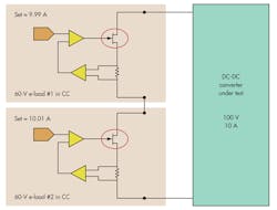
Every e-load is rated for a maximum voltage, such as 60 V. If the dc-dc converter has a 100-V, 10-A output, you might be tempted to put two 60-V e-loads in series (Fig. 2). Each e-load must be set to pull 10 A because they are in series and the same current will flow through them. However, they will never be programmed to the exact same current level due to programming inaccuracies.
So, e-load #1 may go to 9.99 A and e-load #2 may go to 10.01 A. Now, current begins to flow. E-load #1, set to the lower current level of 9.99 A, will control the current and successfully operate in CC. E-load #2, set to the higher current, will try to pull more and more current by lowering its RDS, but it will never achieve its programmed 10.01 A because e-load #1 is limiting its current to 9.99 A. Eventually, e-load #2 will become a near short and operate unregulated.
Since it is a short, the resulting voltage across e-load #2’s terminals will be nearly 0 V. This means virtually all of the 100 V will appear across the terminals of e-load #1. This excess voltage will cause e-load #1 to shut down and could potentially damage the input circuits.
While this example is for two e-loads in series, the situation is the same for three or more. This only goes to prove that you can’t have two or more devices both trying to control/regulate the flow of current through the same path.
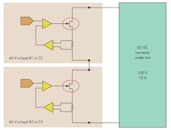
You may be tempted to consider having one e-load in CC and the rest in CV so only one e-load is trying to control the current. But in this configuration, a problem will occur when intentionally turning the e-loads off or if one of the e-loads goes into protection and shuts off unexpectedly.
As soon as the flow of current is interrupted, any e-load set to CC will be driven to act as a short (lowest possible resistance) to try to pull as much current as possible. Meanwhile, any e-load set to CV will be driven to be an open circuit (highest possible resistance) to try to achieve the programmed CV voltage drop across RDS of the FET even when there is no current flow. This will cause the dc-dc converter’s high voltage to appear across the e-loads with the highest resistance due to the voltage divider effect of the e-load resistances in series (Fig. 3).
Summary
It is not safe to operate e-loads in series if the device under test can supply more voltage than the rating of any one e-load, as the whole voltage will eventually appear across one e-load. So, the only safe way to operate in series is to have every e-load be rated for the full voltage of the device under test. But if you have that, you don’t need to put the e-loads in series after all.
Bob Zollo is a product planner with the Power and Energy Division, Electronic Measurements Group, at Agilent Technologies. He is responsible for creating Agilent’s power products roadmap by researching customer and industry trends and developing product plans to meet emerging customer needs. He holds a degree in electrical engineering from Stevens Institute of Technology in Hoboken, N.J. He can be reached at [email protected].
About the Author
Bob Zollo
Solution Architect for Battery Testing, Electronic Industrial Solutions Group
Bob Zollo is solution architect for battery testing for energy and automotive solutions in the Electronic Industrial Solutions Group of Keysight Technologies. Bob has been with Keysight since 1984 and holds a degree in electrical engineering from Stevens Institute of Technology, Hoboken, N.J. He can be contacted at [email protected].


