Engineers often face design goals with conflicting requirements. For instance, take a design that requires an input capacitor to stabilize the bias voltage and present clean dc power to the device’s circuits. During test, the device needs to be subjected to transients to see if it can tolerate disturbances on the dc input voltage.
Related Articles
- Do You Have Enough AC For Your DC?
- What Is An Autoranging Power Supply?
- Bipolar Power Supplies Run The Voltage Gamut
You have to rapidly move the dc bias voltage to simulate noise or a dc disturbance. But with that large input capacitor on the device under test (DUT), it will be difficult to rapidly change the voltage. That capacitor was supposed to prevent rapid changes in voltage. Hence the conflict—how do you change the voltage during test when the capacitor is keeping that from happening?
The Right Power Supply
This file type includes high resolution graphics and schematics.
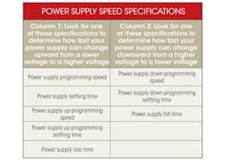
To test under transient conditions, you turn to a power supply that can rapidly change its output voltage. The table’s first column lists the key specifications. But unless the transient condition is only up in voltage, you need to consider how fast the power supply can change its voltage in the downward direction, too.
To quickly change voltage downward, you need a power supply that can sink current back into the power supply to discharge that large input capacitor on the DUT to bring the capacitor voltage down to the desired voltage. You need a power supply with a down-programmer circuit, or a power supply with two-quadrant operation (source current and sink current) or even a four-quadrant supply.
The four-quadrant supply’s voltage can swing from plus to minus, but that doesn’t enable it to go fast. Instead, its ability to sink current (i.e., operate in the quadrant with positive voltage and negative current) allows it to rapidly pull the voltage down on the DUT’s input capacitor. To determine if your power supply will be fast in the downward direction, look for the specifications called out in the second column of the table.
Once you have a fast power supply that can charge and discharge the input capacitor on the DUT, there are still other factors to consider. The voltage on the capacitor is governed by:
I = C * dV/dt
To rapidly change voltage at the required rate of volts per second (dV/dt), you need current. If you want to change the voltage faster, dV/dt gets larger, so the required current gets larger. And as the capacitor gets bigger, the current grows more. With the required current equal to the product of C and dV/dt, it can grow rapidly if you want to quickly change current across a large capacitor. Let’s look at some examples.
Case 1: Charging An Empty Capacitor
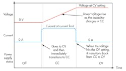
When you first apply the dc bias power to charge a big, empty capacitor, it looks like a dead short. The power supply will not be able to instantaneously drive the voltage to the desired value. (Instantaneously means dV/dt is infinite and therefore the required current is infinite.) So, the supply will go into current limit.
Assuming this is a constant voltage/constant current (CV/CC) supply, it will transition from CV to CC and then charge the capacitor with a constant current. The voltage on the capacitor will climb linearly until its voltage hits the CV voltage setting of the power supply. The supply will then cross over back into CV and the expected operation will continue (see the figure).
This may happen so quickly that you never notice the supply went from CV to CC, charged the capacitor, and then back into CV. If you want to observe this, set your supply’s current limit low and use a big capacitor. You’ll be able to watch the CV to CC to CV state changes and see the linear charging on the capacitor.
Case 2: Modulating DC
The capacitor has been charged and is sitting at its final dc voltage. Now you want to modulate the dc bias voltage on the DUT. Let’s say the desired modulation is to put a sine wave riding on top of the dc. In the automotive world, this test is called alternator whine, where a small sine wave rides on the 12-V dc nominal voltage. The sine-wave amplitude could be 0.5 V p-p, and the frequency is swept up to 20 kHz.
The required current is I = C * dV/dt. If the frequency is 20 kHz, and the voltage swing is 0.5 V, then the approximate dV/dt is 0.5 V/(1/(2 * 20,000 Hz)) = 20,000 volts per second. With C of 1000 µF, it would take 20 A (= C * dV/dt = 1000 uF * 20,000 volts per second). While 20 A is not a large number, it is not related at all to the nominal dc current.
Even if the DUT only required 1 A nominal to operate, the dc source would still need to be able to source and sink20 A just to drive the capacitor up and down by 0.5 V at 20 kHz. If you wanted to put 1 MHz of noise instead, the current would soar to 1000 A.
Summary
When changing the voltage on capacitors, you need to consider how much current will be required. And that current can grow quite large as the capacitor gets large or as the desired rate of change of voltage gets large.
Bob Zollo is a product planner with the Power and Energy Division, Electronic Measurements Group, at Agilent Technologies. He is responsible for creating Agilent’s power products roadmap by researching customer and industry trends and developing product plans to meet emerging customer needs. He holds a degree in electrical engineering from Stevens Institute of Technology in Hoboken, N.J. He can be reached at [email protected].
This file type includes high resolution graphics and schematics.
About the Author
Bob Zollo
Solution Architect for Battery Testing, Electronic Industrial Solutions Group
Bob Zollo is solution architect for battery testing for energy and automotive solutions in the Electronic Industrial Solutions Group of Keysight Technologies. Bob has been with Keysight since 1984 and holds a degree in electrical engineering from Stevens Institute of Technology, Hoboken, N.J. He can be contacted at [email protected].


