Microcontroller Displays Voltage Measurements in Graphical and Digital Formats via Single LED Matrix
This article is part of the Ideas for Design Series: Vol. 3, No. 10.
If the need arises to display measurements in both graphical and digital formats, an LED matrix display offers one of the best solutions. The MSP430G2452 16-bit microcontroller developed by Texas Instruments is a good fit to implement this algorithm, which requires just 400 lines of memory and is based on the Code Composer Studio, a development environment that includes an optimizing C++ compiler in its tool suite (see the listing).
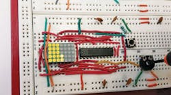
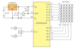
The design uses port P1.3 to read the analog input voltage, which it sees via trimming potentiometer R2 (Fig. 1). After some processing, the voltage reading is sent to a 5x7 common-cathode LED matrix (from Lite-On Electronics) that’s used horizontally to display the voltage in graphical and digital formats. Input voltage ranges from 0 to 3.5 V.
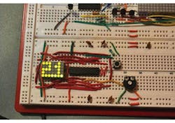
2. The graphic format prevails when the input voltage is changing; here, it shows a voltage reading of 1.7 V, with every dot representing a 0.1-V increment.
When the input voltage is changing 100 mV or more, the graphic format prevails with the voltage displayed as a string of LEDs, where every dot in the matrix represents 100 mV (Fig. 2).
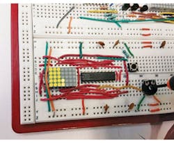
This comes in handy for seeing trends and observing changes. Once the voltage is stable, a digital reading displays as two digits of 5×3 matrix dots, with a resolution of 0.1 V (Fig. 3).
This file type includes high resolution graphics and schematics when applicable.
The processor’s 10-bit analog-to-digital converter (ADC) is configured with reference voltages at VREF+ = VCC and VREF- = VSS, which results in resolution of 3.5/1024 = 3.41 mV per bit. The sampling period was set to 64 clock cycles in the ADC. Once the ADC is turned on, the conversion starts, and after 64 clock cycles, the ADC reading is stored in a variable called ADC_value.
Subsequently, to avoid errors, a “cast” is applied to make it a floating type. Once created in the instruction voltage= (float)ADC_value, it’s transferred to a floating-type variable called “voltage,” which is then multiplied by 0.00341 (the LSB value) to convert the reading to a decimal format. Thus, the result of this product is stored back in the same floating variable “voltage.”
With the method draw(int1,int2,int3,int4,int5,int6,int7), every LED gets assigned a binary weight in each column. To turn on the first LED, its assigned binary weight is “1,” while the 5th LED has a binary weight of 31. Depending on the field, the respective row will be enabled. Placing number 31 instead of int1 turns on all LEDs in that row.
This method invokes another one called select_led(int f, int c), which selects the LEDs that will be on and the row to be activated. This creates a library that stores the figures for numbers 0-9, referring to three variables that will store the binary weight. For example, the figure for number “zero” will have the values [31, 17, and 31].
Since the voltage is stored in a floating-type variable, a call to ftoi(float) is created to separate the integer and decimal parts of a voltage reading into two digits. That’s because the library only allows integer values. A reading like 3.1 V, for example, separates into “3” and “1”, and each digit is stored in a different variable.
The variables named “a1-a7” look for their respective figure in the method number( ), depending on each case. This method assigns their decimal value to them in an integer-type vector int [ ] for that figure—in the decimal part as well as in the integer part. It also invokes the method “period,” which simply turns on the decimal point Led. After establishing the values, the program invokes the method select led(int f, int c). The vector’s value is placed in the file “int c,” including a variable that will be incremented depending on the integer, decimal, or dot part.
For example, if there’s 0.0 Vdc at analog input (P1.3), then the displayed reading should be 0.0. This means the MCU reads the ADC value that’s transferred to the variable voltage, and then it’s multiplied by 0.00341. Since this is a floating-point operation, the result is “0.0,” so the method ftoi(float) is invoked to separate the integer and decimal parts stored in two integer variables (int1, int2).
Next, the method integer_number(int) is invoked, which also calls the method number(int). This is the library containing all of the matrix figures. Finally, in the field int, the value of int1 (the integer part) is allocated. Because it’s zero, it will search for vector “v1” with the following values: V1[0]=31, V1[1]=17, V1[2]=31.
Now the program will enter into a loop cycle “for (i=0, i<=2, i++).” In this cycle, the method select_led(int1,int2) is invoked. However, the fields are substituted by counter “i” and at the same time by a vector with sub index “I,” which invokes select_led(i,v1[i]). This cycle repeats three times and the counter is incremented substituting values as follows:
First running cycle:
select_led(0,v1[0]) //recall that v1[0]=31 so all LEDs will be tuned on row 0.
Second running cycle:
select_led(1,v1[1]) //recall that v1[1]=17 it will turn the top and bottom LED in row 1.
Third running cycle:
select_led(2,v1[2]) //recall that v1[2]=31, it will turn on all LEDs on row 2.
The method period() is invoked and it will call method Select_led(3,1), which will turn on the first LED on row 3. Then it will invoke the method number_dec(int). It works similar to the method integer_number(int), except that the cycle changes to “for (i=4, i<=6, i++),” which corresponds to rows 4, 5, and 6 in the matrix display.
When the ADC input changes more than 100 mV, the MCU displays a graph that starts filling the LEDs vertically, where each one represents 100 mV. This is because the method graph( ) only gives values to seven variables of the integer type, which are then placed into the method draw(int1,int2,int3,int4,int5,int6,int7) .
Ricardo Jimenez-Garcia holds a master’s degree in electronics from Instituto Technologico de Mexicali (ITM). He is an adjunct professor at Imperial Valley College, Imperial, Calif., and is the author of the book “Designing with Speech Processing Chips” published by Elsevier Science Direct. Jimenez-Garcia can be reached at [email protected].
Ivan Romero-Hernandez is a student in Mechatronics Engineering at ITM.


