Dostal's Designs: Compact UPS with Supercap
This video/article is part of Dostal's Design series in Ideas for Design and the TechXchange: Power Supply Design. You can also post a question.
Members can download this article in PDF format.
What you'll learn:
- Applications that require a UPS.
- How a typical UPS is implemented.
- A new, highly integrated backup solution.
In many applications, it’s important for the supply voltage to be continuously available no matter what the circumstances. This isn’t always easy to ensure, though. A new concept can provide an optimal solution for an uninterruptible power supply (UPS) with an extremely compact design.
Several applications require an uninterruptible power supply. One example is the RAID system for redundant data storage, which must be protected so that no data is lost in the event of a power failure at an inconvenient time, such as during data backup activity. Systems with real-time clocks also must be supplied continuously with power. This can come from a battery or another backup solution. Other applications include telemetry applications in the automotive sector and systems for administering medications—for example, controlled insulin pumps used in the healthcare sector.
Figure 1 shows a typical industrial application for an uninterruptible power supply. Here, an industrial sensor is supplied with power. The reliability of the system mainly depends on this sensor’s power supply.
A linear charge regulator IC is used to charge a supercapacitor when there’s available system voltage. If the system voltage drops, the energy from the energy-storage system is raised to the required supply voltage level with a boost regulator.
This system works well, but it’s difficult to implement because many different energy converters are needed. Moreover, in many applications, it’s important that no energy flows from the energy-storage system back to the power supply (depicted in Fig. 1).
As shown in Figure 1, the supercapacitor should only power the sensor circuit and not any other electronics that may be attached to the 24-V line (left side of Fig. 1). The energy-storage system is normally designed to supply the local load and not the complete system attached to the 24-V supply voltage. This makes diode D in Figure 1 necessary.
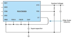
Figure 2 shows a new concept supported by the MAX38889 from Analog Devices (ADI). It’s a highly integrated backup solution called Continua for power rails up to 5 V. A single IC with a few passive external components is all that’s required. The MAX38889 has an integrated half-bridge, operated alternately in highly efficient buck and boost modes.
A complete, operable circuit is illustrated in Figure 3. The logic and the power switches are all integrated, so just a small external chip-scale inductor and a few backup capacitors are required, apart from the supercapacitor.
The integrated high-side power switch is executed with the True Shutdown technology developed by ADI. As a result, the system voltage can be separated from the CAP voltage so that no current flows from the CAP to the system if the CAP voltage is ever higher.
While plenty of backup solutions for various voltage and current ranges exist on the market, the compact MAX38889 Continua backup solution can easily be added to the 5- or 3.3-V supply line with minimal development and implementation effort. It also offers high conversion efficiency of up to 94% in charging and discharging modes to minimize the size and cost of the energy storage.
Check out more video/articles in the Dostal's Design series in Ideas for Design and the TechXchange: Power Supply Design.


