Understand ISO 26262 Hardware-Element Classes to Ensure Safe Designs
Members can download this article in PDF format.
Safety is a critically important aspect of any automotive or industrial application. As automotive and industrial products become more autonomous, designers of these products face increasing pressure to meet standards for functional safety, which involves anticipating what could go wrong and taking steps to reduce risk to an acceptable level. Specific standards that address functional safety include IEC 61508 for industrial applications and ISO 26262 for the automotive industry.
Functional safety addresses two types of faults that can occur in an element such as an integrated circuit:
- Systematic faults result from design errors or flaws in the manufacturing process.
- Random hardware faults are unpredictable yet detectable and preventable using built-in functional-safety mechanisms.
For your functional-safety designs, you can select components that were developed in full compliance with the relevant functional-safety standard as certified by an independent organization such as TÜV SÜD. On the other hand, if you choose parts not developed in accordance with the standard, additional steps can be taken to demonstrate that your system employing these elements meets relevant safety criteria.
Sponsored Resources:
- Functional Safety at TI: Understanding ISO 26262 hardware element classes
- Understanding Functional Safety FIT Base Failure Rate Estimates per IEC 62380 and SN 29500
- Understanding functional safety in automotive and industrial sensing applications
Understanding functional safety in automotive and industrial sensing applicationHardware-Element Classes
ISO 26262 defines three hardware-element classes for such parts. A class I element has few or no states that can be analyzed from a safety perspective without knowledge of its development-process and implementation details. Moreover, it lacks internal safety mechanisms to control or detect failures. A class I element—such as a capacitor, transistor, LDO, PTC temperature sensor, or simple logic gate—doesn’t need to be evaluated regarding functional safety by itself, but it can be evaluated as part of a larger system.
A class II element has few states that can be analyzed from a safety perspective without knowledge of implementation details, and it may have no internal safety mechanisms. However, documentation may exist to support assumptions regarding systematic faults. If you choose a class II element—such as an op amp, data converter, dc-dc converter, or CAN transceiver—be prepared to complete an evaluation plan supported by analysis and testing to show that the element meets the necessary safety requirements.
Class III elements—including microprocessors, SoCs, multichannel PMICs, motor drives, and single-board computers—have many operating modes that are impossible to analyze without knowledge of development-process and implementation details. They also have internal safety mechanisms to control or detect failures. For these elements, be prepared to complete an evaluation plan and take additional steps to demonstrate that the risk due to systemic faults is sufficiently low.
Texas Instruments offers three categories of functional-safety products: functional-safety-capable, functional-safety-managed, and functional-safety-compliant (Fig. 1). Two of these categories map approximately to the three classes of ISO 26262.
Class I elements, with few operating modes and no internal safety mechanisms, approximately map to TI’s functional-safety-capable category. The more complex class II elements also approximately map to TI’s functional-safety-capable category, while class III products approximately map to TI’s functional-safety-managed product category (Fig. 2). A review of concepts such as safety integrity level (SIL) and failure-in-time (FIT) calculation can help you better understand how this mapping works.
Functional-Safety Metrics
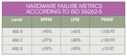
For industrial applications, IEC 61508 defines SILs in a range from SIL 1 to SIL 4, with SIL 4 being the most stringent. Similarly, ISO 26262 defines automotive SILs (ASILs) ranging from ASIL A to ASIL D, with ASIL D being the most stringent. Each SIL or ASIL, in turn, sets limits for additional fault metrics.
A primary input for calculating random-hardware-fault metrics is the base failure rate (BFR), which quantifies a component’s intrinsic reliability under normal operating conditions. BFR is expressed in units of FIT, which is an estimate of the number of failures that could occur in a billion cumulative hours of operation.
BFR is the basis for several other quantitative hardware failure metrics, including single-point fault metric (SPFM), latent fault metric (LFM), and probabilistic metric for random hardware failure (PMHF). The table shows allowable values of these metrics in accordance with ISO 26262.
TI’s functional-safety-compliant products are produced using TI’s functional-safety process, which is certified by TÜV SÜD. These products come with a FIT-rate calculation, comprehensive failure modes, effects and diagnostics analysis (FMEDA), and a functional-safety manual. They also may come with a fault-tree analysis and functional-safety product certificate.
The functional-safety quality-managed and functional-safety-capable categories include products fabricated using TI’s standard quality-managed development flow instead of the certified functional-safety flow. These products come with documentation and analysis that you can use in your own hardware-element evaluation.
Functional-safety quality-managed products include a FIT-rate calculation, FMEDA, and functional-safety manual. Functional-safety-capable products come with a FIT-rate calculation and a die failure-mode distribution or pin failure-mode analysis.
Radar Example
Radar sensing is an application area requiring functional safety in both automotive and industrial markets. TI offers mmWave radar devices specifically designed for automotive and industrial applications that require compliance with ISO 26262 and IEC 61508. These devices come with a functional-safety manual, FMEDA, and FIT estimation. They also offer features such as product function tailoring, safety-mechanism tailoring, and custom diagnostics, enabling you meet application-specific functional-safety requirements.
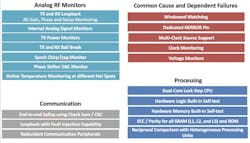
The TI mmWave radar sensors also feature built-in monitoring and loopback schemes that continuously track system functionality to enhance real-time functional-safety operation. On top of that, they reduce loading on the host processor while maintaining overall performance and system efficiency. With the multiple built-in safety mechanisms shown in Figure 3, the devices provide the diagnostic coverage required to meet a random hardware capability as high as ASIL B and SIL 2 at the component level.
Conclusion
Maintaining functional safety in accordance with ISO 26262 and IEC 61508 is critical for automotive and industrial applications. TI offers three categories of functional-safety devices that help maximize design flexibility, two of which approximately map to three hardware-element classes defined in ISO 26262. The devices come with the documentation and analysis you need to complete your own functional-safety evaluations.
Sponsored Resources:


