An accumulation of factors within a test system can produce unacceptable waveform distortion, casting doubt on the validity of the test results.
Present RF immunity standards do not stipulate waveform purity verification other than observation of harmonic content during system calibration. However, there are fundamental differences between the conditions of an actual test run and calibration into an empty chamber.
First, modulation is applied during the test run, demanding more power from the amplifier than during calibration. Second, the presence of the unit under test (UUT) can cause frequency shifts of where chamber peculiarities occur. Third, reflected power from large UUTs can change the operational characteristics of the amplifier. All these factors add up to reduce the certainty that all is well with the applied test waveform.
The topic of test waveform integrity rarely is raised for two reasons:
� Visual inspection on a suitable test instrument at every test frequency would be very time-consuming.
� It is accepted without question that the RF immunity system provider designed in enough power overhead to make waveform distortion negligible.
As a result, very few test laboratories monitor RF immunity test waveforms for change in amplitude or corruption of wave shape.
Testing Methodologies
The two main methodologies used in RF immunity testing are open-loop and closed-loop.
Open-Loop Method
With the open-loop method, a field probe is used to confirm field strength across an imaginary plane perpendicular to the field emanating from the antenna. The input power to the RF amplifier required at each test frequency is recorded.
The EMC software then sets the corresponding recorded input power as it steps the signal generator through each test frequency. Harmonics are monitored during this calibration procedure to ensure that the intended test field dominates at all test frequencies. The UUT then is placed with one face at the measurement plane and monitored for susceptibility to the fields with 1-kHz modulation applied to the test signal. The entire test is repeated for other UUT faces.
The open-loop method makes no attempt to compensate for field changes due to the presence of the UUT. For instance, if more power is required from the amplifier to overcome a chamber peculiarity at one particular test frequency during calibration, UUT reaction with the chamber may cause the peculiarity frequency to shift. The amplifier still will run at the same higher power as during calibration, resulting in an over-test situation.
Similarly, the shift in frequency of the peculiarity will create an under-test situation at the new peculiarity frequency. Also, for UUTs with large reflective surfaces, increased reflected power seen by the amplifier could cause the amplifier gain characteristic to change or protective mechanisms to kick in. A reduction in gain or current clamping due to protective circuits will cause a change in the forward test waveform.
Closed-Loop Method
The closed-loop method is used to maintain constant field strength at the measurement plane despite changes caused by the presence of the UUT. With the UUT in place, data from a field probe is fed back to the EMC software, and the output power of the signal generator changes to lock the field strength at the prescribed value.
There is a hazard with this approach. Under high-reflection conditions, waves reflected by the UUT will combine constructively and destructively with the forward waves. A standing wave will be formed with maxima and minima every half wavelength. For instance, at a test frequency of 1 GHz, there are 10 wavelengths between the antenna and the UUT 3 meters away, resulting in a maximum or minimum every 15 cm.
If, due to reflection or refraction, a minimum coincides with the position of the field probe, the EMC software will increase the power of the signal generator to compensate, pushing the power amplifier toward or into saturation. Saturation will cause waveform distortion as well as over-testing of the UUT. Alternatively, if a maximum occurs at the probe position, the software will react accordingly, and an under-test situation will occur.
Monitoring and Maintaining Test Signal Integrity
Microelectronics and low-cost digital processing open several avenues to monitoring and maintaining test signal integrity. Processing power can come from the grossly underutilized system PC or a microprocessor embedded in the amplifier or elsewhere in the system. The input variables are the test waveform at the amplifier input, the test waveform at the amplifier output, the level of reflected power, and if digital storage is employed, samples of test waveforms taken during calibration.
Circuits for the Open-Loop Method
Waveform Error Warning
Beginning with the open-loop method, the least complex circuit to create is one that alerts the system operator that the test waveform at the amplifier output has changed from that expected.
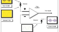
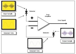
Figure 1 shows a conceptual circuit. The input signal to the amplifier is demodulated to produce a 1-kHz reference signal. A suitably attenuated sample of the output signal also is demodulated and subtracted from the reference signal.
Figure 1. Creating the Error Signal
The resulting error signal provides information on differences in amplitude and waveform shape. This may be recognized as the basis of how a distortion meter works. In the simplest of scenarios, a threshold detector would trip an alarm if the error signal exceeded a preset amount.
Adaptive Predistortion
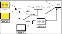
A more elaborate circuit would provide adaptive predistortion. This circuit uses the error signal as feedback to lock the output waveform to that of the input waveform (Figure 2). It works as follows:
Figure 2. Adaptive Predistortion
Any attempt by the attenuated output signal to depart from the reference signal causes a change in the error signal. The change in the error signal alters the input attenuation and, consequently, the overall gain of the circuit combination. This forces the output signal back to the instantaneous amplitude of the input signal. So fundamentally, the signal presented at the actual amplifier input is distorted adaptively by changes in the error signal, hence the name of this linearization technique.
Adaptive predistortion allows the amplifier to operate well into its compression region, significantly reducing the need for power overhead. The reason for the reduced need can best be explained by example:
Assume an amplifier has a gain of 50 dB at a particular frequency. During testing, the system provides the test signal at this frequency on the assumption that the amplifier has a fixed 50-dB gain. If the amplifier goes into compression and the gain reduces to 48 dB, the test signal peaks, which require the greatest power, are amplified at 2 dB less than they should be. This results in distortion of the output waveform peaks.
The system designer is well aware of this. To avoid this problem, ample power overhead usually is specified to ensure the amplifier operates way down in its linear range, far away from the compression zone. With adaptive predistortion, the compressed gain zone no longer is out of bounds, and changes in amplifier performance due to high reflected power are corrected automatically.
Bear in mind that a 150-W RF amplifier will begin to compress at less than 100 W so the reward is well worth the effort. As a precaution, the threshold trip still should be incorporated to flag the operator should the predistortion circuit be unable to correct for extreme amplifier compression.
Circuits for the Closed-Loop Method
Adaptive Predistortion
Adaptive predistortion also is suitable for closed-loop operation, serving as a loop within a loop. That is, if the field-controlled loop requires an increase in field strength, the EMC software increases the signal from the signal generator. This, in turn, increases the reference signal, resulting in an error signal that increases the test signal at the output of the amplifier. The EMC software can control the field-loop time constant to prevent oscillation due to the two loops chasing each other.
Harmonic Cancellation
Another feature that can be added to allow greater use of the amplifier compressed gain area is harmonic cancellation. Similar to the feedforward scheme used in base-station amplifiers in the cell-phone industry, signals caused by nonlinearities in the amplifier are cancelled by injecting identical signals in anti-phase.
Feedforward was developed for use in the cell-phone industry in response to the need to keep down base-station amplifier power overhead. This is an extraordinarily complex process in voice and data telecommunications. But with RF immunity testing, the input signal and the products caused by the amplifier are entirely deterministic; that is, they are known or can be anticipated ahead of time. This is an advantage when it comes to designing a cancellation system.
Producing harmonic frequencies of the input signal is relatively easy using frequency-doubler and frequency-tripler circuits. These harmonics then can be inverted and added to the input signal to cancel the anticipated harmonics at the amplifier output. This is where digital signal processing and software control excel.
An optimization algorithm can optimize the cancellation process while the EMC software slowly brings up the level of the test field, allowing time for several optimization cycles. This feature also is suitable for use in the open-loop method.
Smart Immunity System
There is a hazard with the closed-loop method if the field-monitor position coincides with a field null or field peak. A smart immunity system could address this by correcting for the existence of a standing wave.
If the values of the peaks and nulls are measured, the field strength of the incident wave at the measurement plane can be calculated. The EMC software then could insert this value into the closed loop.
To measure the peaks and nulls, their position must be moved to coincide with that of the field probe. A standing wave can be moved around in the chamber simply by changing the phase of the input signal. Algorithms can be written to complete all the necessary tasks.
Again, the EMC software would bring up the field strength slowly, allowing time for the algorithms to provide the field loop with the correct field strength. The smart system could be incorporated inside the amplifier itself or offered as an aftermarket bolt-on fitted around the amplifier.
The list of suggested circuits is by no means exhaustive, and other techniques borrowed from other industries could apply equally well.
Conclusion
A supplier to the EMC test industry may recommend a 150-W amplifier, even though only 60 W of linear power are required at the antenna connector to produce 10 V/m at 3 meters. Buyers of RF immunity systems may question the apparently excessive power overhead, especially if convinced by marketing slogans that there is no consequence to large amounts of reflected power. If doubtful that the entire overhead is vital, intrepid test-laboratory managers may be tempted to hire or borrow a 100-W or even an 80-W amplifier to see if it will do the trick.
The real issue here, though, is the inability to automatically check for test waveform integrity during a test run. With one or more of the suggested circuits added, it could well turn out that lower power overhead is entirely feasible.
No broadband RF amplifier can withstand all levels of reflected power without some consequence. At the very least, the test operator should be informed that the output waveform has changed. It then is up to the test operator to investigate and use the knowledge gained from system familiarity to see if corrective action is required.
About the Author
Thomas Mullineaux, the chief writer at HighTechWriter, is an RF engineer with 15 years experience in leading design teams. HighTechWriter, 3332 Florista St., Los Alamitos, CA 90720, 562-400-4501, e-mail: [email protected]
April 2005


