High Voltage: Dealing with Partial Discharge
Members can download this article in PDF format.
What you'll learn:
- What is partial discharge?
- Methods for measuring PD.
- How PD impacts high-voltage cables.
Partial discharge (PD) is evidence of a degrading insulation system, which could trigger costly repairs and predictively cause an electrical breakdown of any high-voltage apparatus.
Although PD may be small in size, it can certainly deteriorate insulation over time. Ultimately, it will lead to a system failure. If this condition is left unchecked, the insulation failure may result in not just a loss of supply to processes or customers, but it may also endanger staff members.
For designers to better understand partial discharge, the most important standard that every expert will need is “IEC 60270: High-voltage test techniques – Partial discharge measurements” (link leads to a preview of the text). This standard applies to the measurement of PD in electrical appliances or systems when testing with AC voltages as high as 400 Hz or with DC voltages.
IEC 60270 defines partial discharge as “a localized electrical discharge that only partially bridges the insulation between conductors and which will or will not occur adjacent to a conductor.”
Measuring PD by Applying AC Voltages
Let’s look at a test circuit for AC voltages according to the IEC 60270 standard, with measurement of PD in electrical appliances or systems when testing with AC voltages as high as 400 Hz.9
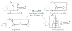
Figure 1 provides an overview of the four basic measuring circuits according to IEC 60270. Z is known as the blocking impedance that’s positioned between the source and the test object. This blocking impedance reduces any high-frequency interference from the voltage source as well as limiting the propagation of transient signals into that voltage source.
Ca is the capacitance of the device under test (DUT) and Ck is the coupling capacitor, and together with a measuring impedance (Zm), it decouples the PD signals and then converts them into voltage pulses for analysis with a partial discharge detector (M).
The most common circuit for measuring PD is shown in the top left of Figure 1. In that image, the measuring impedance Zm is shown in series with Ck, the coupling capacitor. Both are in parallel with the DUT.
When the measuring impedance is placed in series with the ground of the DUT (Fig. 1, top right), detection sensitivity can be increased. Beware, though, that the measuring impedance in this configuration could experience serious damage from any unexpected breakdown.
A higher measurement sensitivity can be achieved with a bridge impedance (Fig. 1, lower left) when connecting to the low voltage side of the DUT and the coupling capacitor. This setup will significantly help reduce any external electromagnetic influences.
In transformer testing, if capacitively graded bushings are available, they may be used as the coupling capacitor for the PD measurement circuit (Fig. 1. bottom right).
High-Voltage Equipment Partial Discharge: HV Cable
The definition of high-voltage PD is a discharge that doesn’t fully bridge the space between electrodes. This discharge can occur within a gas-filled void, within an insulating material, or when surrounding an electrode within a gas environment. A corona is defined as the partial discharge around an electrode within a gas environment as well.
It hasn’t yet been proven that the relationship between PDs and the long-term failure of electrical insulation is an issue. However, it’s suspected that PDs may be the major reason for aging and ultimate failure of the electrical insulation.
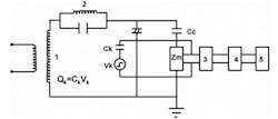
Measurements of PD activity within test programs are an item for most kinds of high-voltage/radio-frequency equipment. Figure 2 shows an experimental arrangement showing a simplified circuit that is able to detect “partial discharge.”8
In Figure 2, transformer 1 is free from internal discharges. Resonant filter 2 prevents any pulses that may start from the capacitance of Transformer 1 bushings and windings. Cx, in resonant filter 2, is the test object, Cc is the coupling capacitor, and Zm is the detection impedance. The signal, which is developed across the Zm impedance, is passed the through bandpass filter (3) and amplifier (4), and will be displayed on a cathode ray oscilloscope (5) or can be counted via a pulse-counter multichannel analyzer unit.
Although the maximum and minimum charge will remain virtually constant, the average charge of the PD rises with the increase in applied voltage of the cable. Now, we can determine that this increase in charge may lead to an increase in current and could end in a short circuit when the cable is working at its maximum capacity or for an extended period of time.
Power-Cable PD Characteristics
Next, we’ll look at the partial-discharge characteristics of a 10-kV power cable, with defects, under a very low frequency voltage and oscillating wave voltage.3
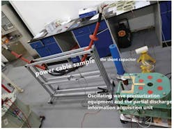
PD power-cable defect characteristics are compared under an oscillating wave voltage and a very low frequency voltage. Samples of 10-kV heat-shrinkable, cold-shrinkable power cable with axial and radial knife-mark defects, and water-intake defects with no defects, were tested under a very low frequency and oscillating wave voltage. The test platform is shown in Figure 3.
This study carried out PD tests with the PD inception voltage, maximum PD volume, and PD waveforms being recorded and measured.
Test results showed that the PD inception voltage of a 10-kV power cable under the oscillating wave voltage was ower than that of the very low frequency voltage. Now, under the same fixed voltage, the maximum PD of the oscillating voltage is larger, while the number of PD pulses are higher. In addition, the PD waveform is far denser than one at a very low frequency voltage.
The results demonstrate that for the same cable sample, the PD threshold voltage that’s under the oscillation wave voltage is lower than that of a very low frequency voltage.
References
1. “Enabling high voltage signal isolation quality and reliability,” Tim Bonifield, Texas Instruments, 2017.
2. “Classification and comparison of AC and DC partial discharges by pulse waveform analysis,” Science Direct, International Journal of Electrical Power & Energy Systems, Volume 125, February 2021, 106518
3. “Partial Discharge Characteristics of 10kV Power Cable Defects under Very Low Frequency and Oscillating Wave Voltage,” 2021 IEEE 4th International Electrical and Energy Conference (CIEEC).
4. “Determination of Particle Discharge Inception Characteristics of Poly metric Insulating Surfaces based on Detection Threshold Discharge Current,” 978-1-6654-0750-2/22, IEEE 2022.
5. “Experimental Investigation of Partial Discharge Inception Characteristics on Polymeric Insulating Surfaces under Positive Ramp High Voltages,” 2022 IEEE International Conference on High Voltage Engineering and Applications (ICHVE), 2022.
6. “Ultra High Frequency Partial Discharge Sensors based on Various Microstrip Patch Antenna Designs,” 2021 3rd International Conference on High Voltage Engineering and Power Systems (ICHVEPS).
7. “Commissioning of UHV Indoor Double Shielded Laboratory for Radio Interference Voltage and Partial Discharge Measurement,” P Rajamani, K A Aravind, K Urukundu, Pradeep Nirgude, B Krisha, and P Shivaprasad, IEEE 2019.
8. “Partial discharge in High Voltage Equipments-HV Cable,” Proceedings of the 9th International Conference on Properties and Applications of Dielectric Materials, July 19-23,2009, Harbin, China.
9. ”The Basics of Partial Discharge Testing,” HV Technologies Inc.
About the Author

Steve Taranovich
Freelance Technical Writer, Phoenix Information Communication LLC
Steve is a contributing editor to Electronic Design.
Author of the non-fiction “Guardians of the Right Stuff,” a true story of the Apollo program as told by NASA and Grumman Corp. engineers, an astronaut, and technicians.
Experienced Editor-In-Chief of EETimes/Planet Analog and Senior Technical Editor at EDN running the Analog and Power Management Design Centers from 2012 to 2019.
A demonstrated history in electronic circuit design and applications for 40 years, and nine years of technical writing and editing in industry. Skilled in Analog Electronics, Space-related Electronics, Audio, RF & Communications, Power Management, Electrical Engineering, and Integrated Circuits (IC).
1972 to 1988 worked as a circuit design engineer in audio (8 years) and microwave (8 years). Then was Corporate Account Manager/applications engineer for Burr-Brown from 1988 to 2000 when TI purchased Burr-Brown. Worked for TI from 2000 to 2011.
Strong media and communication professional with a BEEE from NYU Engineering in 1972 and an MSEE from Polytechnic University in 1989. Senior Lifetime member of IEEE. Former IEEE Long Island, NY Director of Educational Activities. Eta Kappa Nu EE honor society member since 1970.


