Because vision systems don�t become bored or tired, they are ideal solutions to many repetitive inspection applications. For example, checking the clarity and orientation of printing on a component could easily be done by a human operator. However, after several parts, the operator�s interpretation of good/bad inspection criteria would have changed from that used to evaluate the first few. If, in addition to inspecting a quantity of components, there also is a time limit or the parts are mixed with other items in varying orientations, human operators don�t do a very good job.
As components become smaller, it is more difficult for an operator to distinguish between good and bad parts and assemblies. Especially if different sections of a component need to be examined under a microscope, simply ensuring that the correct orientation has been achieved is time-consuming. An automated vision system can directly index to the intended location. Most importantly, it doesn�t forget what the image at the previous position looked like when making comparisons.
Also, there are applications that require data to be recorded faster and in greater detail than any operator can do. For example, line scan cameras often are used to examine a web of material being processed at high speed. People can inspect the finished product, but they can�t detect manufacturing flaws on the fly in real time.
These representative capabilities of vision systems�repetitive test and inspection, accurate measurement and comparison, and high-speed image acquisition�are discussed in depth through three examples of actual end-user applications.
Capturing a Transient Event Quickly
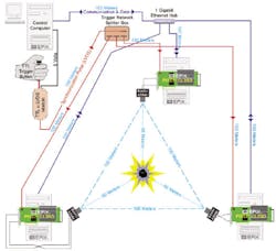
In this example, the object was to record the detailed behavior of a combustion event�a fire or explosion�in a large field. Figure 1 shows the arrangement of the major elements of the vision system supplied by EPIX of Buffalo Grove, IL. The company designed and built the system based on three Basler A504kc Color Cameras and three PIXCI CL3SD Frame Grabbers.
The application posed several challenges. The customer demanded a minimum frame rate of 2,000 frames/s for a record with high temporal resolution. Images needed to be recorded simultaneously from three locations for a 360� composite view. Cameras were to be spaced 100 meters apart to allow room for the targeted apparatus. A total of 12 GB of image data needed to be recorded at video rate. The three cameras had to be controlled from a single location at a safe distance.
Acquiring the Images
The Basler A504kc Camera can capture at 500 frames/s with a 1,280-line � 1,024-pixel resolution. The area of interest is programmable in one-line increments vertically and in 10-pixel increments horizontally. The required 2,000 frames/s were achieved with an area of interest of 256 lines � 340 pixels. A total of 49,344 frames was captured per camera, providing three simultaneous views of the event with duration of 24.6 s.
Breaking the Camera Link Barrier
At the time the system was designed, the camera link specification was new and only addressed camera designs up to 64 b on eight data channels. The Basler A504kc Camera needed to output 80 data bits on 10 channels. Basler and EPIX worked together to tap 16 b provided by camera link hardware that are not used by the Full camera link specification.
The designer of the PIXCI CL3SD Board, EPIX�s Chuck Petersen, explained: �There were no cameras capable of 80 b of data at the time Basler and EPIX wrote the spec. The A504kc Camera and the CL3SD Board were made to work on the camera link connectors because it could be done and because nobody had done it before.�
The PIXCI CL3SD Frame Grabber
The PIXCI CL3SD Board allows the Basler Camera, which generates 625 MB/s, to be used on any computer with a standard PCI bus. Because PCI data transfer is limited to 100 MB/s in a 32-b/33-MHz system, the CL3SD Board provides 4 GB of high-speed memory for local image storage. Video-rate data transfer occurs between the camera and the on-board SDRAM. Subsequent to data capture, images are transferred from the board into the computer at the slower rates allowed by the PCI bus chip set.
Bridging the Distances
With cameras spaced 100 meters apart, EPIX chose to use three local computers, each with its own CL3SD Board, Windows XP OS, and XCAP-Std Imaging Program. The two camera link cables that connect each A504kc Camera to its CL3SD Board were kept to 3 meters.
System Control
The control computer was connected to the three remote computers with a Gigabit Ethernet (GbE) network that served two purposes. First, it gave the operator local access to each of the three remote desktops. Windows XP installed on each of the four computers provided remote access to the XCAP-Std Imaging Program running on the three remote machines. Second, the GbE network allowed the image data captured on the remote computers to be conveniently transferred to the control computer�s hard disks.
In addition, EPIX provided an LVDS trigger circuit that allowed synchronization of all three cameras. With one press of a button, the control operator signals all three remote stations to trigger at the same time. The trigger pulse can be preconfigured to capture data in one of three ways: a full sequence after the trigger, a full sequence before the trigger, or with the trigger centered within the sequence.
Improved Version Pending
The PIXCI CL3SD Board remains the only frame grabber that allows use of the Basler A504kc Camera on the 32-bit/33-MHz PCI bus. EPIX recently introduced the PIXCI E4 Imaging Board that provides four-lane data transfer on the PCI Express bus. The PIXCI E4, when combined with 64-b addressing, will allow high-speed video rate capture at up to 800 MB/s into more than 32 GB of computer memory (memory limit constrained by the host computer).
Electrical Contact Inspection
GOEPEL electronic contracted to extend the capabilities of a functional tester for electronic assemblies used in a car control unit. In addition to the tester�s original capabilities, a vision system was required to determine the type of electronic assembly being inspected, ensure the presence and placement of electrical contact shielding, check two pairs of contacts for mechanical alignment, and read a data matrix code.
Only one camera could be used because space was limited within the enclosure, as can be seen in Figure 2, and no increase in size was allowed. GOEPEL chose a National Instruments (NI) CVS 1454 Compact Vision System and an AVT Marlin F-46B Camera with a compatible IEEE 1394 interface. In this application, the maximum 4.5-m cable length associated with 1394 cameras was more than sufficient given the compact nature of the installation.
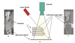
Of the new requirements, verifying the correct vertical position and alignment of the two pairs of contacts was the most challenging. To accomplish this, a laser diode source was used to illuminate the contact pairs at an oblique angle. The setup is shown in Figure 3a.
If the contacts are correctly positioned, the light reflected from them forms a distinctive pattern easily measured by the camera. If instead, one or more of the contacts is bent up or down from the desired position, the light will be reflected from a different location on the contact, changing the pattern. The degree to which the two patterns do not match is a function of the displacement of one or more contacts.
Assuming the simplified case of only vertical displacement, for an angle of incidence ? of the laser light, the illuminated spot will shift horizontally by
?d = ?h / secant ?
where: ?h = the contact height offset
Although this equation deals only with vertical displacement, in the actual application, triangulation is used to determine height information as well as horizontal offset and angular displacement. NI�s Vision Builder application was used to develop the image analysis algorithm.
Figures 3b and 3c show two views of the contact assembly. The difference in appearance highlights the importance of choosing the type of lighting most appropriate for a given application. The laser diode source is a key element in the triangulation procedure used to pass or fail the assembly. In addition, information also is derived from the LED-illuminated image to meet the complete list of inspection requirements.
In this application, a standard spectral response is suitable because a monochrome camera is sensitive to visible red laser light. In addition, the field of view is small, so the camera�s 780 � 582-pixel resolution is adequate, and a high-resolution camera is not needed. With this camera and the triangulation algorithms running in the CVS 1454 Vision System, the total time for image acquisition and inspection is less than 500 ms.
Orienting and Counting Small Parts
New Jersey-based Compex annually manufactures more than 10 million single-layer components used in high-frequency RF, microwave, telecommunications, and fiber-optics products. To increase volume and accelerate delivery time, Compex recently implemented new automated inspection systems based on compact machine vision sensor technology.
�Packaging has been one of the major delays for us in getting product out the door,� said David Gordon, the company�s general manager. �A lot of our time was spent manually inspecting components to ensure they were oriented properly before being placed into packages and later counting components in packages to make sure customers were getting exactly what they had ordered.�
Previous Approaches
Compex had implemented a proprietary vision inspection system in 2000 to ensure components were correctly oriented before being robotically loaded into packaging. However, different types of substrate materials including quartz and ceramic as well as highly reflective gold plating would confuse the vision system and cause failures. Unfortunately, it also had trouble ignoring various marks and scratches on the surfaces of the production feed track, and additional failures resulted.
�The vision system we had been using was basically just a pixel counting system, so even if a component was incorrectly oriented or off-center, the system would accept the part if the pixels added up,� explained Mr. Gordon. �We had to constantly tweak the light sources for this system, and ultimately the system�s limitations demanded an upgrade.�
Vision Comes Full Circle
In early 2005, the company began working with Serview, a Cognex Certified Vision Integrator. Serview Engineering Manager Brian LeBlanc said, �We used the equipment Compex had already purchased, retooling it with new machine vision and programmable logic controllers (PLCs). The stand-alone Cognex In-Sight Vision Sensors we selected have the right toolset for us and run without a PC for anything other than product changeover or viewing inspection results.�
Orientation Plus
The main components of the new orientation system include an In-Sight 1000 Vision Sensor, Compex�s existing Cartesian robot, a vibratory feed bowl and track, an air blow-off for part rejection, and an Allen-Bradley Micrologix PLC. A Cognex I/O module links the In-Sight sensor with the PLC. A PC monitors the inspection, performs product changeover, and runs the In-Sight Explorer Vision Software application as well as a custom graphical user interface.
The Serview team ultimately settled on a combination of Xenon strobe and fiber-optic lighting so the full range of Compex components could be inspected without setup changes. This combination provided white light that could be accurately synchronized via the I/O module, supporting proper image formation for the various component types.
First, the vision sensor verifies the orientation of the component and then measures critical dimensions including the overall size and the metal coating. Serview Director of Operations Steve LeBlanc explained, �Tolerances are an issue when inspecting components as small as 0.015″ square. We make dimensional measurements as part of the inspection process and reject defective parts that are chipped or out of tolerance. This gives an extra level of quality inspection that finds more defects than we originally expected to see.�
Both the orientation and dimensional inspections were set up using various edge-detection and histogram vision software tools, part of the standard In-Sight 1000 Tool Library. The orientation system is fed from a vibratory feed bowl. Once a component moves under the In-Sight 1000 Sensor, an image of the component is captured and sent to the sensor�s on-board processor where the vision tools analyze the image. Operators can view the inspection in real time.
The PLC signals the robot to grip a correctly oriented part and place it onto a film ring or waffle pack. The entire inspection and placement time, from image acquisition of a good chip to robot placement, is approximately 300 ms limited by material-handling speeds.
If the component is upside down or stacked on top of another, for example, the vision sensor fails the part, a red LED appears on the inspection monitor, and the part automatically recycles back into the feed bowl. A Serview-designed calibration program allows operators to easily reset the camera lens magnification within 5 s if the lens goes out of adjustment.
Inspection That Really Counts
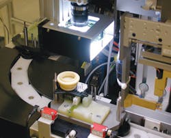
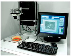
Farther downstream, packaging containing thousands of components travels through Compex�s new automated, tabletop, stand-alone counting system just before being shipped (Figure 4.) �One of the key design considerations with this system was building in the flexibility to automatically count smaller and smaller components in the future,� said Mr. LeBlanc. �The high-resolution In-Sight Sensor was a good solution because it would give the company this leeway.
�The system combines the sensor with LED backlighting and a PC running a custom-designed Visual Basic program,� he continued. �In response to operator selection of a given job, all set-up parameters, such as brightness settings, change dynamically.�
Because the components are so small and closely packed, images are preprocessed with a grayscale morphology tool, which provides the necessary feature separation for a blob tool to work reliably. As the sensor counts, it also verifies that the components are the correct size and not touching.
It typically takes less than 20 s to perform the whole sequence of alignment and counting. The image of the package is saved to disk, and count data is saved in an SQL database, giving Compex a permanent record of every package they ship. Serview is in the process of integrating the vision count data so it is printed onto a label with the bar code and serial number of the package.
Conclusion
The vision systems have eliminated a major bottleneck in Compex�s capa-bility to ship quickly, and labor savings in the packaging area alone are approximately 80%. �We knew that implementing these systems successfully would be challenging since previous attempts at developing similar systems did not succeed.� Mr. LeBlanc said. �Serview engineers focused on working with Compex to understand their processes and part types, and this allowed us to design and tune the lighting and software to cover their full range of products.�
|
FOR MORE INFORMATION |
| Cognex | In-Sight Sensor | www.rsleads.com/605ee-210 |
| EPIX | PIXCI� CL3SD Frame Grabber | www.rsleads.com/605ee-211 |
| GOEPEL | AOI System Integration | www.rsleads.com/605ee-212 |
| Serview | Machine Vision System Integration | www.rsleads.com/605ee-213 |
Summary
Through a detailed look at three very different kinds of vision applications, a large number of design constraints have been highlighted. Although there always is a central theme, other factors add complications.
In the parts-counting solution, the Cognex In-Sight Sensor was combined with sophisticated lighting so all of the manufacturer�s components could be inspected by the same system. Linear laser illumination was key to triangulation needed in the GOEPEL inspection example. In contrast, lighting for the high-speed recording application was provided entirely by the combustion event at the center of the field.
The speed with which part alignment could be verified and the part transferred to packaging was important but not critical to Compex. System reliability and accuracy were clearly at the top of the vision-system specification because of the customer dissatisfaction and manual labor costs associated with the previous inspection and counting approaches.
Like Compex, GOEPEL�s automotive customer relied on the vision system accuracy. Because of the customer�s manufacturing process, bad contact assemblies would not be found until the car was completely finished, so they had to be inspected correctly. However, high speed often is necessary. A key metric in the EPIX application was the 2,000 frames/s image acquisition rate.
Many more comparisons could be made, for example, with regard to distributed vs. local computing resources. Serview�s Brian LeBlanc commented that a PC only was needed to change the test program or view the results of the Cognex In-Sight Sensors. Otherwise, the sensor runs its inspection program without a PC. At the opposite extreme, because of the high data rate associated with the Basler camera output, EPIX provided 4 GB of local storage as well as a separate computer at each camera site.
When deciding if a vision system is appropriate for your application, clearly outline the prime requirements, but don�t forget there are many others. Will you need to inspect similar components for which the present lighting may not be optimum? Is the amount of data or its speed going to influence the system design as much as image analysis, for example? Will a sufficiently powerful vision system fit in the space available? In short, make sure you thoroughly understand all the system constraints before committing to an application solution.
May 2006
