An Introduction to LTE-Advanced: The Real 4G
Download this article in .PDF format
LTE is likely the most complex wireless system ever developed. It incorporates features that could not have been economically implemented as recently as a decade ago. Today, with large-scale ICs, LTE can be easily accommodated in basestations and battery-powered handsets alike. The complexity is a function of the advanced wireless methods used as well as the many options and features that can be implemented.Long-Term Evolution (LTE) is being adopted around the world as the primary cell-phone communications service. Multiple 2G and 3G cellular radio methods are being phased out as carriers build their new LTE networks. It will be years before this expansion is complete, and older radio technologies like GSM and CDMA will coexist with LTE for a while (see “The Evolution Of LTE,” www.demo.electronicdesign.com/content/evolution-lte ).
In the meantime, the next phase of the LTE standards as put forth by the Third Generation Partnership Project (3GPP) is ready to be deployed.1 Called LTE-Advanced (LTE-A), this significant upgrade to the LTE standard will provide more speed and greater reliability. While LTE-A is still being developed, some LTE-A service could begin late in 2013.
Table Of Contents
- Frequency & Bandwidth
- Modulation
- MIMO
- Data Rate
- Access
- TD-LTE
- LTE-Advanced
- LTE-A Design Challenges
- Voice Over LTE
- Waiting for 5G
- References
LTE operates in some of the existing cellular bands as well as newer bands. Specific bands have been designated for LTE (see the table). Different carriers use different bands depending upon the country of operation and the nature of their spectrum holdings. Most LTE phones use two of these bands, and they aren’t the same from carrier to carrier. For instance, Verizon’s iPhone 5 uses different bands than AT&T’s iPhone 5.
Most of the bands are set up for frequency division duplexing (FDD), which uses two separate bands for uplink and downlink. The spacing between FDD channels in bands 1 through 28 varies considerably depending on carrier spectrum holdings. Bands 33 through 44 are used for time division duplexing (TDD), so the same frequencies are used for both uplink and downlink.
LTE is a broadband wireless technology that uses wide channels to achieve high data rates and accommodate lots of users. The standard is set up to permit bandwidths of 1.4, 3, 5, 10, 15, and 20 MHz. The carrier selects the bandwidth depending on spectrum holdings as well as the type of service to be offered. The 5- and 10-MHz widths are the most common. Some bandwidths cannot be used in different bands.
LTE uses the popular orthogonal frequency division multiplex (OFDM) modulation scheme. It provides the essential spectral efficiency to achieve high data rates but also permits multiple users to share a common channel. OFDM divides a given channel into many narrower subcarriers. The spacing is such that the subcarriers are orthogonal, so they won’t interfere with one another despite the lack of guard bands between them. This comes about by having the subcarrier spacing equal to the reciprocal of symbol time. All subcarriers have a complete number of sine wave cycles that upon demodulation will sum to zero.
In LTE, the channel spacing is 15 kHz. The symbol period therefore is 1/15 kHz = 66.7 µs. The high-speed serial data to be transmitted is divided up into multiple slower streams, and each is used to modulate one of the subcarriers. For example, in a 5-MHz channel, up to 333 subcarriers could be used but the actual number is more like 300. A 20-MHz channel might use 1024 carriers. The modulation on each can be quadrature phase-shift keying (QPSK), 16-phase quadrature amplitude modulation (16QAM), or 64-state quadrature amplitude modulation (64QAM) depending on the speed needs.
OFDM uses frequency and time to spread the data, providing high speeds and greater signal reliability (Fig. 1). For each subcarrier, the data is sent in sequential symbols where each symbol represents multiple bits (e.g., QPSK 2 bits, 16QAM 4 bits, and 64QAM 6 bits.) The basic data rate through a 15-kHz subcarrier channel is 15 kbits/s. With higher-level modulation, higher data rates are possible.
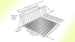
1. LTE transmits data by dividing it into slower parallel paths that modulate multiple subcarriers in the assigned channel. The data is transmitted in segments of one symbol per segment over each subcarrier.
Data to be transmitted is allocated to one or more resource blocks (RBs). An RB is a segment of the OFDM spectrum that is 12 subcarriers wide for a total of 180 kHz. There are seven time segments per subcarrier for a duration of 0.5 ms. Data is then transmitted in packets or frames, and a standard frame contains 20 time slots of 0.5 ms each. An RB is the minimum basic building block of a transmission, and most transmissions require many RBs.
The only practical way to implement OFDM, though, is to do it in software. The fast Fourier transform (FFT) handles the basic process. The transmitter uses the inverse FFT, while the receiver uses the FFT. The algorithms are implemented in a digital signal processor (DSP), an FPGA, or an ASIC designed for the process. The usual techniques of scrambling and adding error-correcting codes are implemented as well.
OFDM was chosen for LTE primarily due to its reduced sensitivity to multipath effects. At the higher microwave frequencies, transmitted signals can take multiple paths to the receiver. The direct path is the best and preferred but multiple objects may reflect signals, creating new signals that reach the receiver somewhat later. Depending on the number of reflected signals, their strengths, their ranges, and other factors, the signals at the receiver may add in a destructive way, creating fading or signal dropout.
The multipath effects occur when the signals reach the receiver all within the time for one symbol period. A symbol is a modulation state that is either an amplitude, a phase, or an amplitude-phase combination representing two or more bits. When the multipath effects lead the signals to arrive at the receiver spread over several symbol periods, inter-symbol interference (ISI) occurs, producing bit errors. These issues can be overcome with error detecting and correcting codes, but these codes add to the complexity of the system. An equalizer at the receiver that collects all the received signals and delays them so they all add can also correct for this problem but only further complicates the process.
Spreading the signals in the form of multiple subcarriers over a wide bandwidth reduces these effects, especially if the symbol rate on each subcarrier is longer as it is in OFDM. If the multipath effects occur in less than one symbol period, no equalizer is needed. Time or frequency shifts such as those produced by the Doppler effect in a moving vehicle cause frequency variation of the subcarriers at the receiver. This shift in frequency results in the loss of orthogonality and subsequently bit errors.
LTE mitigates this problem by adding a cyclical prefix (CP) to each transmitted bit sequence. The CP is a portion of an OFDM symbol created during the DSP process that is copied and added back to the front of the symbol. This bit of redundancy allows the receiver to recover the symbol if the time dispersion is shorter than the cyclical prefix. OFDM then can be implemented without the complex equalization that can also correct for this problem.
While LTE’s downlink uses OFDM, the uplink uses a different modulation scheme known as single-carrier frequency-division multiplexing (SC-FDMA). OFDM signals have a high peak to average power ratio (PAPR), requiring a linear power amplifier with overall low efficiency. This is a poor quality for battery-operated handsets. While complex, SC-FDMA has a lower PAPR and is better suited to portable implementation.2, 3
LTE incorporates multiple-input multiple-output (MIMO), which uses two or more antennas and related receive and transmit circuitry to achieve higher speeds within a given channel. One common arrangement is 2x2 MIMO, where the first number indicates the number of transmit antennas and the second number is the number of receive antennas. Standard LTE can accommodate up to a 4x4 arrangement.
MIMO divides the serial data to be transmitted into separate data streams that are then transmitted simultaneously over the same channel. Since each signal path is different, with special processing they can be recognized and separated at the receiver. The result is an increase in the overall data rate by a factor related to the number of antennas. This technique also mitigates the multipath problem and adds to the signal reliability because of the diversity of reception.
The difficultly in implementing MIMO arises because of the small size of the handset and its limited space for antennas. Already, most smart phones include five antennas including those for all the different cellular bands plus Wi-Fi, Bluetooth, GPS, and perhaps near-field communications (NFC). Most phones probably won’t feature more than two LTE MIMO antennas, and their inclusion will depend on whether or not they can be spaced far enough apart to preserve spatial diversity with sufficient isolation between them. Of course, it’s easier to use more basestation antennas. A typical LTE arrangement appears to be 4x2 to provide optimal coverage with the space available.
The data rate actually used or achieved with LTE depends on several features: channel bandwidth, modulation type, MIMO configuration, and the quality of the wireless path. In the worst-case situation, data rate could be only a few megahertz. But under good conditions, data rate can rise to more than 300 Mbits/s. On average, most practical LTE downlink rates range from 5 to 15 Mbits/s, which is faster than some fixed Internet access services using cable or DSL.
Access refers to using the same channel to accommodate more than one user. This is effectively a multiplexing method. Standard methods include frequency division multiple access (FDMA), time division multiple access (TDMA), and code division multiple access (CDMA). GSM uses TDMA by dividing a single channel into multiple time slots. In 2G and 3G CDMA systems, code division uses unique coding for each user with a single bandwidth.
OFDM now offers OFDM Access (OFDMA), which uses some of the available subcarriers and time slots within those subcarriers for each user. The number of subcarriers and time slots used depends on multiple factors. In any case, it’s usually possible to accommodate up to hundreds of users per channel bandwidth.
Most LTE will be of the FDD variety at least in the U.S., Europe, and parts of Asia. However, TD-LTE is being widely implemented in China and India because of the nature of their spectrum availability. TD-LTE conserves spectrum and provides for more users per megahertz. The LTE standards include a definition for TD-LTE. Some U.S. carriers will use TD-LTE including Clearwire and Sprint.
LTE-A builds on the LTE OFDM/MIMO architecture to further increase data rate. It is defined in 3GPP releases 10 and 11. There are five major features: carrier aggregation, increased MIMO, coordinated multipoint transmission, heterogeneous network (HetNet) support, and relays.
Carrier aggregation combines up to five 20-MHz channels into one to increase data speed. These channels can be contiguous or non-contiguous as defined by the carrier’s spectrum assignments. With maximum MIMO assignments, 64QAM, and 100-MHz bandwidth, a peak downlink data rate of 1 Gbit/s is possible.
LTE defines MIMO configurations up to 4x4. LTE-A extends that to 8x8 with support for two transmit antennas in the handset. Most LTE handsets use two receive antennas and one transmit antenna. These MIMO additions provide future data speed increases if adopted.
HetNet support refers to support for small cells in a larger overall heterogeneous network. The HetNet is an amalgamation of standard macrocell basestations plus microcells, metrocells, picocells, femtocells, and even Wi-Fi hotspots. This network increases coverage in a given area to improve connection reliability and increased data rates.
Coordinated multipoint transmission, also known as cooperative MIMO, is a set of techniques using different forms of MIMO and beamforming to improve the performance at cell edges. It uses coordinated scheduling and transmitters and antennas that aren’t collocated to provide greater spatial diversity that can improve link reliability and data rate.
Relays use repeater stations to help coverage in selected areas, especially indoors where most calls are initiated. LTE-A defines another basestation type called a relay station. It is not a complete basestation but a type of small cell that will fit in the HetNet infrastructure and provide a way to boost data rates and improve the dependability of a wireless link.
Some deployment of LTE-A is expected in late 2013 with increasing adoption in 2014 and beyond. LTE-A is forward and backward compatible with basic LTE, meaning LTE handsets will work on LTE-A networks and LTE-A handsets will work on standard LTE networks.
LTE solves many problems in providing high-speed wireless service. There is no better method, at least for now, but it does pose multiple serious design issues. The greatest problem is the necessity of having to use multiple bands that often are widely spaced from one another. As a result, multiple antennas, multiple power amplifiers, multiple filters, switching circuits, and, sometimes, complex impedance matching solutions are required. Each cellular operator specifies cell phones for its spectrum.
In addition, the power amplifiers (PAs) must be very linear if error vector magnitude (EVM) is to be within specifications for the various multi-level modulation methods used. Linear amplifiers are inefficient and consume the most power in the phone except for the touchscreen. The need to cover multiple bands necessitates the use of multiple PAs. Battery life in an LTE phone is typically shorter as a result. The need to include MIMO also means additional antennas and PAs.
Solutions to these problems lie in fewer yet more efficient PAs. Also, wider-bandwidth antennas solve the multiband problem. Companies like Ethertronics and SkyCross are designing tunable antennas as well to cover multiple bands with a single structure.
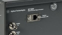
Another challenge is test. Several test companies have created systems to test LTE systems with MIMO, which can be a particularly complex process. One of the greatest challenges is testing the higher-level MIMO configurations. LTE-A permits up to 8x8 MIMO. Agilent’s N7109A multi-channel MIMO analyzer is designed to work with the company’s 89600 vector signal analyzer (VSA) and related Signal Studio software to test LTE-A in all its various configurations (Fig. 2).
2. The Agilent Technologies N7109A multi-channel LTE signal analyzer handles up to 8x8 MIMO channels.
LTE is a packet-based IP data network. It doesn’t include a voice service yet, though one is planned. Today, if you’re using an LTE smart phone, you’re still using the existing 2G or 3G network for what is called circuit-switched voice service. Voice over LTE (VoLTE) eventually will be implemented. VoLTE is just Voice over Internet Protocol (VoIP) over LTE, and it will operate simply as a data application on the IP network.
While a VoLTE protocol has been defined, implementation requires major engineering decisions and network changes, mostly concerning maintaining voice connections for older non-LTE phones for some extended period. Particularly tricky are the changes that will allow LTE phone users to get voice service if they move into an area with no LTE.
When VoLTE is available, subscribers could initiate a call using the LTE system but drive out of the LTE coverage area. Systems must be able to hand that call off to a traditional voice network. The mechanism for this, network software called circuit-switched fallback (CSFB), is now available on most networks. Another issue is getting VoLTE into the handsets. VoLTE requires a separate chip in the phone, and few phones have such a capability today.
VoIP also requires a vocoder, a circuit that is essentially an analog-to-digital converter (ADC) to digitize the voice signal and a digital-to-analog converter (DAC) to convert the digital voice back into analog voice for the user. A vocoder also incorporates voice compression, a technique that effectively minimizes the number of bits used to represent voice. Voice then can be transmitted faster but at lower data rates so it doesn’t occupy much bandwidth.
LTE uses the Adaptive Multi-Rate (AMR) vocoder, which also is used in GSM systems and other 3GPP standards. It has a variable bit-rate capability from 1.8 to 12.2 kbits/s. Digitized voice is then assembled into AMR packets and then into IP packets that are scheduled into a transmission sequence. A call is allocated to some of the OFDMA subcarriers and to some of the time slots within the bit streams of each subcarrier.
All of the needed phone and network changes will take time to implement. Therefore, VoLTE isn’t widespread. Carrier MetroPCS has it now on its LTE network and Verizon has VoLTE in trials, as do most other major carriers. However, there will be very little VoLTE activity until 2014 and beyond.
It will take a decade or more for LTE and especially LTE-A to dominate cellular coverage. Furthermore, new LTE releases are yet to come. In addition, some provisions of current LTE releases have yet to be implemented, such as self-organizing networks (SONs), which make networks easier to plan, configure, optimize, and manage.
With SON, all basestations would be self-configuring taking into account nearby basestations and using internal algorithms to heal, self-optimize, and adapt to new nearby stations and other conditions. The small-cell movement is definitely LTE-based, and extensive deployment with SON is yet to come. In addition, new higher-frequency spectrum such as 3550 to 3650 MHz will be found, making it possible to extend 4G well into the future.
In the meantime, research continues into the “next big thing,” more specifically the fifth generation (5G) of cellular wireless. 5G may simply stay on the same path as 4G and LTE, using higher frequencies and wider bandwidths to achieve even higher data rates. With semiconductor technology still viable at ever-smaller IC feature sizes, operation well into the hundreds of gigahertz is possible.
Already, advanced millimeter wave (30 to 300 GHz) systems are functioning with advanced chipsets in short-range personal-area networks (PANs) for home video transfer (60 GHz), automotive radar (77 GHz), and cellular/hotspot backhaul (80 GHz). Some think the 28-GHz and 38-GHz spectrum segments offer good opportunities for cellular. Because of the higher frequencies, range is shorter, meaning more but smaller cell sites. However, by using higher-gain antenna arrays and beamforming, coverage will be reliable and the available bandwidth will permit download data rates as high as 10 Gbits/s. It’s something to look forward to.
1. Third Generation Partnership Project, www.3gpp.org
2. Agilent Technologies Inc., LTE and the Evolution to 4G Wireless, Agilent Technologies, 2009.
3. Dahlman, Erik et al., 3G Evolution: HSPA and LTE for Mobile Broadband, Academic Press/Elsevier, 2007.
4. 4G Americas, www.4gamericas.org
5. Webb, William, Wireless Communications: The Future, John Wiley & Sons Inc., 2007.
About the Author

Lou Frenzel
Technical Contributing Editor
Lou Frenzel is a Contributing Technology Editor for Electronic Design Magazine where he writes articles and the blog Communique and other online material on the wireless, networking, and communications sectors. Lou interviews executives and engineers, attends conferences, and researches multiple areas. Lou has been writing in some capacity for ED since 2000.
Lou has 25+ years experience in the electronics industry as an engineer and manager. He has held VP level positions with Heathkit, McGraw Hill, and has 9 years of college teaching experience. Lou holds a bachelor’s degree from the University of Houston and a master’s degree from the University of Maryland. He is author of 28 books on computer and electronic subjects and lives in Bulverde, TX with his wife Joan. His website is www.loufrenzel.com.
Comment About the Article
To join the conversation, and become an exclusive member of Electronic Design, create an account today!

Leaders relevant to this article: